
Product Card

UBS Equipment Identication Chapter 1: Introduction
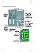
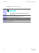
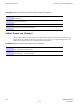
Figure 1 -7 DMI Front P anel
LMT
IDI/SSI1
SSI2
TEST
XMI1/DC XMI2 RS232-2
RS232-1
+27VDC
INST
ST ALM
ti-cdma-06111.eps
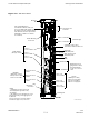
Mounting Tab
TOP
1/4-T urn Fastener
(Retains DMI Chassis
to DMI Cage)
MMI Serial Debug
Ports (RJ45)
Note 2
+27 V DC Input
Power From PDU
(mini-Molex)
Ethernet 10/100 BaseT
Debug Ports (RJ45)
Note 2
LMT
TEST
Serial Backhaul;
Traffic & Control Data
(VHDCI Typel)
To/From SSI-1
To/From SSI-2
Mounting Tab
NOTES:
1. Equipment shown is typical. The actual equipment appearance may vary slightly.
2. The debug ports are intended to be used primarily for testing or debugging purposes by Motorola.
These ports may be used in the field for maintenance purposes by customers. Carefully follow written
procedures when using these ports in the field. Failure to do so could result in an inoperable FRU.
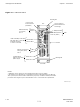
BOTTOM
Handle
To/From XMI-2
To/From XMI-1
LEDs
ST (Status)
ALM (Disk Alarm)
INST (Instance)
CPRI 1.2288 Gbps serial data
links (SFP Type). Carries XMI
baseband I & Q data
as well as control data
RS232-2
RS232-1
1 -24 68P09283A63 -5
FOA A UG 2007