
Product Card

1X UBS Macro B T S Optimization/A TP UBS Equipment Identication
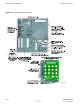
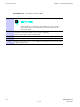
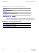
Figure 1 -6 XMI Front P anel
ti-cdma-06106.eps
M
o
u
n
tin
g
RX EXP IN
RX EXP OUT
TOP
MMI
(RJ45)
CONTROL( 9-pin D-type)
To/From TX Combiner; Future Use
LMT (RJ45)
ALM (Alarm) LED
STA (Status) LED
RX Expansion Ports
(ganged mini-coaxial)
To/From RX Splitter
TXD (ganged MCX-type)
To/From TX Combiner; Future Use
(For proper XMI TX RF Outputs operation,
the TXD port must be terminated with
TXD Attenuator, Motorola part number
5888774T01, if XMI is not cabled to
TX Combiner)
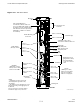
(+)
(-)
+27V DC Input Power
From PDU
HSL2; to/from DMI-2
(HSSDC2 Type)
HSL1; to/from DMI-1
RX DIV
(QMA-Type Coaxial)
Always used on XMI 2;
Only used on XMI 1 if
XMI 2 is not equipped
RX 1; from
Sector 1 IDRF
RX 2; from
Sector 2 IDRF
RX 3; from
Sector 3 IDRF
RX MAIN
(QMA-Type Coaxial)
Always used on XMI 1;
Never used on XMI 2
RX 1; from Sector
1 IDRF
RX 2; from Sector
2 IDRF
RX 3; from Sector
3 IDRF
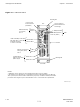
TX-3; to
Sector 3 IDRF
TX-1; to
Sector 1 IDRF
Handle Mounting
Screw Hole
H
andle Mounting
Screw Hole
TX RF Outputs
NOTE:
1. Equipment shown is typical. The
actual equipment appearance may
vary slightly.
(QN-type coaxial)
Mounting Tab
BOTTOM
INST (Instance) LED
2. The debug ports are intended to be used
primarily for testing or debugging purposes
by Motorola.
These ports may be used in the field for
maintenance purposes by customers.
T
a
b
or RX
Cr
o
s
s
-
c
o
n
n
e
c
t
ca
b
l
e
TX-2; to
Sector 2 IDRF
68P09283A63 -5 1 -23
FOA A UG 2007