X UBS Macro BTS Optimization/ATP UBS Equipment Identication UBS Component Identication The UBS is comprised of the following modules (see Figure 1-2): • Power Distribution Unit (PDU) • DMI (Digital Module Internal) • XMI (Transceiver Module Internal) • SSI (Site Span I/O) • IDRF (Integrated Duplexers & RF Filters) • CRMS (Cellular Remote Monitoring System) • External GPS (Optional) • QHSO (Optional) 68P09283A63-5 1-21 FOA AUG 2007
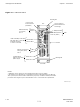
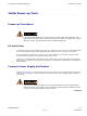
UBS Equipment Identication Chapter 1: Introduction Figure 1-5 UBS Site Span I/O Panel SSI (fron t p a n e l) S PAN 37-P in Co nne ctor T1/E1 ba la nce d S pa n I/O.
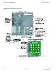
1X UBS Macro BTS Optimization/ATP UBS Equipment Identication Figure 1-6 XMI Front Panel Mounting Tab TOP TXD (ganged MCX-type) To/From TX Combiner; Future Use (For proper XMI TX RF Outputs operation, the TXD port must be terminated with TXD Attenuator, Motorola part number 5888774T01, if XMI is not cabled to TX Combiner) (+) (-) +27V DC Input Power From PDU HSL2; to/from DMI-2 Handle Mounting Screw Hole (HSSDC2 Type) HSL1; to/from DMI-1 CONTROL( 9-pin D-type) To/From TX Combiner; Future Use TX-3
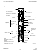
UBS Equipment Identication Chapter 1: Introduction Figure 1-7 DMI Front Panel Mounting Tab +27 V DC Input Power From PDU (mini-Molex) 1/4-T urn Fastener (Retains DMI Chassis to DMI Cage) RS232-2 INST ST ALM ALM (Disk Alarm) RS232-1 +27VDC MMI Serial Debug Ports (RJ45) Note 2 TOP INST (Instance) LEDs XMI1/DC XMI2 To/From XMI-2 Serial Backhaul; Traffic & Control Data (VHDCI Typel) LMT SSI2 TEST IDI/SSI1 Ethernet 10/100 BaseT Debug Ports (RJ45) Note 2 Handle TEST To/From XMI-1 LMT CPRI
Chapter 2 Preliminary Operations ■ ■ ■ ■ ■ ■ ■ ■ ■ ■ ■ ■ ■ ■ ■ ■ ■ ■ ■ ■ ■ ■ ■ ■ ■ ■ ■ ■ ■ ■ ■ ■ ■ ■ ■ ■ ■ ■ ■ ■ ■ ■ ■ ■ ■ ■ ■ ■ ■ ■ ■ ■ ■ ■ ■ ■ ■ ■ ■ ■ ■ ■ ■ ■ ■ ■ 68P09283A63-5 AUG 2007 2-1 FOA
Introduction Chapter 2: Preliminary Operations Introduction ■ ■ ■ ■ ■ ■ ■ ■ ■ ■ ■ ■ ■ ■ ■ ■ ■ ■ ■ ■ ■ ■ ■ ■ ■ ■ ■ ■ ■ ■ ■ ■ ■ ■ ■ ■ ■ ■ ■ ■ ■ ■ ■ ■ ■ ■ ■ ■ ■ ■ ■ ■ ■ ■ ■ ■ ■ ■ ■ ■ ■ ■ ■ ■ This section first verifies proper frame equipage. Cell Site Types Sites are configured as omni, 2–sector or 3–sector with a maximum of two carriers.
1X UBS Macro BTS Optimization/ATP Pre-Powerup Tests Pre-Powerup Tests ■ ■ ■ ■ ■ ■ ■ ■ ■ ■ ■ ■ ■ ■ ■ ■ ■ ■ ■ ■ ■ ■ ■ ■ ■ ■ ■ ■ ■ ■ ■ ■ ■ ■ ■ ■ ■ ■ ■ ■ ■ ■ ■ ■ ■ ■ ■ ■ ■ ■ ■ ■ ■ ■ ■ ■ ■ ■ ■ ■ ■ ■ ■ ■ Objective This procedure checks for any electrical short circuits and verifies the operation and tolerances of the cell site and UBS power supply units prior to applying power for the first time.
Pre-Powerup Tests Chapter 2: Preliminary Operations Procedure 2-1 DC Power Pre–test (UBS) When handling circuit boards and modules, be sure to wear a grounding strap to prevent damages caused by Electrostatic Discharge (ESD). 1 Verify that unit is a DC powered unit. Physically verify that all DC power sources supplying power to the UBS are OFF or disengaged. 2 Ensure that all available circuit breakers on PDU are disengaged (pulled out). 3 Verify that DC power cable is properly connected.
1X UBS Macro BTS Optimization/ATP Initial Power-up Tests Initial Power-up Tests ■ ■ ■ ■ ■ ■ ■ ■ ■ ■ ■ ■ ■ ■ ■ ■ ■ ■ ■ ■ ■ ■ ■ ■ ■ ■ ■ ■ ■ ■ ■ ■ ■ ■ ■ ■ ■ ■ ■ ■ ■ ■ ■ ■ ■ ■ ■ ■ ■ ■ ■ ■ ■ ■ ■ ■ ■ ■ ■ ■ ■ ■ ■ ■ Power-up Procedures Potentially lethal voltage and current levels are routed to the UBS equipment. This test must be performed with a second person present, acting in a safety role.
Initial Power-up Tests Chapter 2: Preliminary Operations Procedure 2-2 Procedure for Common Power Supply Verication 1 Physically verify that all DC power sources supplying the UBS are OFF or disengaged. 2 Visually inspect input cables, verify correct input power polarity. (Cables should be marked.) 3 Engage all available circuit breakers on PDU. 4 After power is applied to the UBS, use a DMM to verify power supply output voltages are within specifications.
Chapter 3 LMF Operation ■ ■ ■ ■ ■ ■ ■ ■ ■ ■ ■ ■ ■ ■ ■ ■ ■ ■ ■ ■ ■ ■ ■ ■ ■ ■ ■ ■ ■ ■ ■ ■ ■ ■ ■ ■ ■ ■ ■ ■ ■ ■ ■ ■ ■ ■ ■ ■ ■ ■ ■ ■ ■ ■ ■ ■ ■ ■ ■ ■ ■ ■ ■ ■ ■ ■ 68P09283A63-5 AUG 2007 3-1 FOA
Optimization/Calibration Introduction Chapter 3: LMF Operation Optimization/Calibration Introduction ■ ■ ■ ■ ■ ■ ■ ■ ■ ■ ■ ■ ■ ■ ■ ■ ■ ■ ■ ■ ■ ■ ■ ■ ■ ■ ■ ■ ■ ■ ■ ■ ■ ■ ■ ■ ■ ■ ■ ■ ■ ■ ■ ■ ■ ■ ■ ■ ■ ■ ■ ■ ■ ■ ■ ■ ■ ■ ■ ■ ■ ■ ■ ■ Introduction This section describes for using the Line Maintenance Facility (LMF) to verify the proper operation of the installed UBS system.
1X UBS Macro BTS Optimization/ATP Preparing the LMF Preparing the LMF ■ ■ ■ ■ ■ ■ ■ ■ ■ ■ ■ ■ ■ ■ ■ ■ ■ ■ ■ ■ ■ ■ ■ ■ ■ ■ ■ ■ ■ ■ ■ ■ ■ ■ ■ ■ ■ ■ ■ ■ ■ ■ ■ ■ ■ ■ ■ ■ ■ ■ ■ ■ ■ ■ ■ ■ ■ ■ ■ ■ ■ ■ ■ ■ Overview Before optimization can be performed, the LMF application software must be installed and configured on a computer platform meeting Motorola-specified requirements (see Recommended Test Equipment and Software in Chapter 1 Introduction).
Preparing the LMF Chapter 3: LMF Operation Figure 3-1 LMF Folder Structure ti-cdma-05823.eps The loads folder and all the folders below it are no longer contained on the LMF CD as of LMF 2.9.0.0. When installing LMF software on a system that has never contained LMF software before, the user will need to create these folders manually. When installing a new version of LMF onto a PC already containing LMF software, any existing folders will be unaffected.
1X UBS Macro BTS Optimization/ATP Preparing the LMF WinLMF Operating System Installation This section provides information and instructions for installing and updating the LMF software and files. First Time Installation Sequence: 1. Install Java Runtime Environment (JRE) 2. Install U/WIN K-shell emulator (optional) 3. Install LMF application programs Any time U/WIN is re-installed, the LMF application software must also be re-installed.
LMF to UBS Connection Chapter 3: LMF Operation LMF to UBS Connection ■ ■ ■ ■ ■ ■ ■ ■ ■ ■ ■ ■ ■ ■ ■ ■ ■ ■ ■ ■ ■ ■ ■ ■ ■ ■ ■ ■ ■ ■ ■ ■ ■ ■ ■ ■ ■ ■ ■ ■ ■ ■ ■ ■ ■ ■ ■ ■ ■ ■ ■ ■ ■ ■ ■ ■ ■ ■ ■ ■ ■ ■ ■ ■ LMF to UBS Connection Follow the procedure in Procedure 3-2 to establish LMF to UBS connection. Procedure 3-2 LMF to UBS Connection Procedure 1 Verify that the WinLMF computer has an Ethernet port.
1X UBS Macro BTS Optimization/ATP Using WinLMF Using WinLMF ■ ■ ■ ■ ■ ■ ■ ■ ■ ■ ■ ■ ■ ■ ■ ■ ■ ■ ■ ■ ■ ■ ■ ■ ■ ■ ■ ■ ■ ■ ■ ■ ■ ■ ■ ■ ■ ■ ■ ■ ■ ■ ■ ■ ■ ■ ■ ■ ■ ■ ■ ■ ■ ■ ■ ■ ■ ■ ■ ■ ■ ■ ■ ■ Basic WinLMF Operation LMF Coverage in This Publication — All references to the LMF in this publication are for the CDMA application program Operating Environments — The LMF application program allows the user to work in the two following operating environme
Using WinLMF Chapter 3: LMF Operation Online Help - Task oriented online help is available in the LMF by clicking on Help from the menu bar. The LMF Display and the UBS UBS Display - When the LMF is logged into a UBS, a frame tab is displayed. The frame tab will be labeled with Frame, the UBS number, a dash, and the frame number (for example, Frame-812-1 for UBS 812, RFMF 1). There is only one frame for the UBS, so there will only be one tab.
1X UBS Macro BTS Optimization/ATP Using WinLMF CLI Format Conventions The CLI command can be broken down in the following way: • verb • device including device identifier parameters • switch • option parameters keywords equal signs parameter values Spaces are required between the verb, device, switch, and option parameters. A hyphen is required between the device and its identifiers.
Using WinLMF Chapter 3: LMF Operation Figure 3-3 WinLMF Icon ti-cdma-LMF_UBS_Supp ort.eps Figure 3-4 Local Terminal (Login Screen) ti-cdma-06193.
1X UBS Macro BTS Optimization/ATP Using WinLMF UBS Login from the GUI Environment Follow the procedure in Procedure 3-3 to log into a UBS when using the GUI environment. Procedure 3-3 UBS GUI Login Procedure The LMF computer Network Interface Card (NIC) IP address is set to 128.0.0.48, subnetmask 255.255.255.128. Ping UBS frame (128.0.0.2) from PC (128.0.0.48) Disable/Stop all rewalls and other applications (e.g. BlackICE) which may block UDP / TCP transfers.
Using WinLMF Figure 3-5 Chapter 3: LMF Operation Network Interface Selection ti-cdma-01683.
1X UBS Macro BTS Optimization/ATP Using WinLMF Figure 3-6 FTP Server ti-cdma-06188.
Using WinLMF Chapter 3: LMF Operation Figure 3-7 Frame Selection ti-cdma-01687.
1X UBS Macro BTS Optimization/ATP Figure 3-8 Using WinLMF Local Terminal GUI ti-cdma-06194.
Using WinLMF Chapter 3: LMF Operation Figure 3-9 Invasive Mode Selection ti-cdma-06190.
1X UBS Macro BTS Optimization/ATP Using WinLMF Figure 3-10 Invasive Mode Message Window ti-cdma-06189.
Using WinLMF Chapter 3: LMF Operation LMF Menus and Options The following figures display the menus and options available to the user. Figure 3-11 displays the selections available under the BTS menu. Figure 3-11 BTS Menu ti-cdma-01682.
1X UBS Macro BTS Optimization/ATP Using WinLMF Figure 3-12 displays the choices that can be selected for testing. Figure 3-12 Select Menu ti-cdma-06198.
Using WinLMF Chapter 3: LMF Operation Figure 3-13 displays the actions for the DMI. Figure 3-13 Device Menu - DMI (HDModem) ti-cdma-01685.
1X UBS Macro BTS Optimization/ATP Using WinLMF Figure 3-14 displays the actions for the XMI. Figure 3-14 Device Menu - XMI ti-cdma-01686.
Using WinLMF Chapter 3: LMF Operation Figure 3-15 displays the choices for the manually configuring equipment. Figure 3-15 Tools Menu - Options ti-cdma-06201.
1X UBS Macro BTS Optimization/ATP Using WinLMF Figure 3-16 displays the receive tests for the UBS. Figure 3-16 Tests Menu - RX ti-cdma-06199.
Using WinLMF Chapter 3: LMF Operation Figure 3-17 displays the transmit tests for the UBS. Figure 3-17 Tests Menu - TX ti-cdma-06200.
1X UBS Macro BTS Optimization/ATP Using WinLMF Figure 3-18 through Figure 3-21display the various UTIL menu choices that allow analysis of the UBS under test. Figure 3-18 Util Menu - Power Meter ti-cdma-06204.
Using WinLMF Chapter 3: LMF Operation Figure 3-19 Util Menu - Test Equipment ti-cdma-06205.
1X UBS Macro BTS Optimization/ATP Using WinLMF Figure 3-20 Util Menu - Examine ti-cdma-06203.
Using WinLMF Chapter 3: LMF Operation Figure 3-21 Util Menu - Edit ti-cdma-06202.eps Logging Out Logging out of a UBS can only be accomplished from the Graphical User Interface (GUI) mode. The GUI and CLI environments use the same connection to a UBS. If a GUI and the CLI session are running for the same UBS at the same time, logging out of the UBS environment will log out of it for both.
1X UBS Macro BTS Optimization/ATP Using WinLMF Logging Out of a UBS from the GUI Environment Follow the procedure in Procedure 3-4 to logout of a UBS when using the GUI environment. Procedure 3-4 UBS GUI Logout Procedure 1 Click on File on the Local Terminal menu bar. 2 Click the Exit item in the pull-down menu. UBS will perform a soft reset.
Download Code to UBS Chapter 3: LMF Operation Download Code to UBS ■ ■ ■ ■ ■ ■ ■ ■ ■ ■ ■ ■ ■ ■ ■ ■ ■ ■ ■ ■ ■ ■ ■ ■ ■ ■ ■ ■ ■ ■ ■ ■ ■ ■ ■ ■ ■ ■ ■ ■ ■ ■ ■ ■ ■ ■ ■ ■ ■ ■ ■ ■ ■ ■ ■ ■ ■ ■ ■ ■ ■ ■ ■ ■ The process of downloading code to a UBS consists of two principal steps: 1. Code transfer to the UBS followed by distribution to the devices 2.
1X UBS Macro BTS Optimization/ATP Download Code to UBS The UBS code load should always be synchronized with the download from the OMC-R before leaving the UBS site. Refer to Reset All Devices and Initialize Site Remotely on page 5-8 for the procedure to do this. Procedure 3-5 Download Code 1 In the menu bar of the Local Terminal BTS window, select BTS > Download Code... 2 If prompted that the “Following operation may overwrite NECB, NECJ, LIF, and calibration files on the BTS”, click Yes.
Test Equipment Set Up Chapter 3: LMF Operation Test Equipment Set Up ■ ■ ■ ■ ■ ■ ■ ■ ■ ■ ■ ■ ■ ■ ■ ■ ■ ■ ■ ■ ■ ■ ■ ■ ■ ■ ■ ■ ■ ■ ■ ■ ■ ■ ■ ■ ■ ■ ■ ■ ■ ■ ■ ■ ■ ■ ■ ■ ■ ■ ■ ■ ■ ■ ■ ■ ■ ■ ■ ■ ■ ■ ■ ■ Connecting Test Equipment to the UBS The following equipment is required to perform optimization: • LMF • Communications system analyzer model supported by the LMF • Non-radiating transmit line termination load • Directional coupler and in-li
1X UBS Macro BTS Optimization/ATP Test Equipment Set Up Supported Test Equipment Optimization and ATP testing for CDMA2000 1X sites or carriers may be performed using the following test equipment: • Advantest R3267 Analyzer with Advantest R3562 Signal Generator • Agilent E4406A with E4432B Signal Generator • Agilent 8935 series E6380A communications test set (formerly HP 8935) with option 200 or R2K and with E4432B signal generator for 1X FER • Agilent E7495A or Agilent E7495B communications test s
Test Equipment Set Up Chapter 3: LMF Operation Test Equipment Preparation See Appendix D Test Equipment Preparation for specific steps to prepare each type of test set and power meter to perform calibration and ATP. The Agilent E7495A communications test set requires additional setup and preparation. This is described in detail in Appendix D Test Equipment Preparation.
1X UBS Macro BTS Optimization/ATP Test Equipment Set Up Automatic Cable Calibration Refer to Calibrate Test Cabling using Communications System Analyzer on page 3-64 for automatic cable calibration procedures using a communications test set. Manual Cable Calibration If manual cable calibration is required, refer to Calibrate Test Cabling Using Signal Generator & Spectrum Analyzer on page 3-69 for procedures to use a spectrum analyzer and signal generator.
Test Equipment Set Up Chapter 3: LMF Operation Figure 3-23 TX Calibration Test Setup – Agilent 8935 TEST SETS TRANSMIT (TX) SET UP AGILENT 8935 SERIES E6380A (FORMERLY HP 8935) POWER SENSOR 100-W ATT (MIN) NON-RADIA TING RF LOAD HP-IB TO GPIB BOX POWER METER (OPTIONAL)* TX TEST CABLE OUT 50 Ω TERM.
1X UBS Macro BTS Optimization/ATP Figure 3-24 Test Equipment Set Up TX Calibration Test Setup – Agilent E4406A and Advantest R3267 TEST SETS TRANSMIT (TX) SET UP AGILENT E4406A POWER SENSOR 100-W ATT (MIN) NON-RADIA TING RF LOAD POWER METER (OPTIONAL)* TX TEST CABLE OUT 30 DB DIRECTIONAL COUPLER 50 Ω TERM.
Test Equipment Set Up Chapter 3: LMF Operation Figure 3-25 TX Calibration Test Setup – Agilent E7495A TEST SETS TRANSMIT (TX) SET UP POWER SENSOR AGILENT E7495A TX TEST CABLE POWER METER PORT 1 RF OUT COMMUNICATIONS SYSTEM ANALYZER 100-W ATT (MIN.) NON-RADIA TING RF LOAD INTERNAL ETHERNET CARD PORT 2 RF IN OR TX TEST CABLE 30 DB DIRECTIONAL COUPLER 50 Ω TERM.