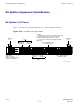
RX Splitter Equipment Identication Chapter 1: Overview RX Splitter Equipment Identication ■ ■ ■ ■ ■ ■ ■ ■ ■ ■ ■ ■ ■ ■ ■ ■ ■ ■ ■ ■ ■ ■ ■ ■ ■ ■ ■ ■ ■ ■ ■ ■ ■ ■ ■ ■ ■ ■ ■ ■ ■ ■ ■ ■ ■ ■ ■ ■ ■ ■ ■ ■ ■ ■ ■ ■ ■ ■ ■ ■ ■ ■ ■ ■ RX Splitter I/O Panel Figure 1-14 shows the wide band (800 MHz-to-2.1 GHz) RX splitter I/O panel. Figure 1-14 Mounting Tab RX splitter front panel detail NOTES: 1. All RX splitter connectors are ganged mini-coaxial. 2.
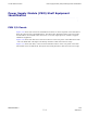
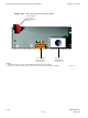
1X UBS Macro BTS FRU Power Supply Module (PSM) Shelf Equipment Identication Power Supply Module (PSM) Shelf Equipment Identication ■ ■ ■ ■ ■ ■ ■ ■ ■ ■ ■ ■ ■ ■ ■ ■ ■ ■ ■ ■ ■ ■ ■ ■ ■ ■ ■ ■ ■ ■ ■ ■ ■ ■ ■ ■ ■ ■ ■ ■ ■ ■ ■ ■ ■ ■ ■ ■ ■ ■ ■ ■ ■ ■ ■ ■ ■ ■ ■ ■ ■ ■ ■ ■ PSM I/O Panels Figure 1-15 shows I/O connectors and PSM slot locations on the front panel of the UBS Macro BTS –48 V DC and 220 V AC PSM shelves.
Power Supply Module (PSM) Shelf Equipment Identication Figure 1-15 Rack Mounting Flange Chapter 1: Overview –48 V DC and 220 V AC PSM shelves front panel detail AC or -48 V DC PSM Shelf (front view) PSM SHELF (9-pin sub-D Connector) NOTE 1 Rack Mounting Flange Filler Panel Captive Retaining Thumbscrew PSM Captive Retaining Thumbscrew PSM Handle PSM Handle PSM 1 ALARM & CONTROL (50-pin Connector) NOTE 2 Connects to ALARM & CONTROL Connector on SSI NOTES: 1.
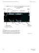
1X UBS Macro BTS FRU Power Supply Module (PSM) Shelf Equipment Identication Figure 1-16 –48 V DC PSM shelf rear panel detail +27 V DC Output Power Cable (shown cut away) To PDU _ 0 VDC + 27 VDC HAZARD OF ELECTRICAL SHOCK WITH COVERS REMOVED _ -48 VDC 0 VDC -48 VDC Input Power Connector (Blue) 68P09283A64-3 ti-cdma-05916.
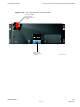
Power Supply Module (PSM) Shelf Equipment Identication Figure 1-17 Chapter 1: Overview 220 V AC PSM shelf rear panel detail +27 V DC Output Power Cable (shown cut away) To PDU _ 0 VDC + 27 VDC HAZARD OF ELECTRICAL SHOCK WITH COVERS REMOVED _ 0 VDC + 27 VDC HAZARD OF ELECTRICAL SHOCK WITH COVERS REMOVED +27 V DC Output Power Connector (Orange) Note 2 AC Input Terminal Block Protective Cover NOTES: 1. Equipment shown is typical. The actual equipment appearance may vary slightly. 2.
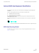
1X UBS Macro BTS FRU Optional RGPS Head Equipment Identication Optional RGPS Head Equipment Identication ■ ■ ■ ■ ■ ■ ■ ■ ■ ■ ■ ■ ■ ■ ■ ■ ■ ■ ■ ■ ■ ■ ■ ■ ■ ■ ■ ■ ■ ■ ■ ■ ■ ■ ■ ■ ■ ■ ■ ■ ■ ■ ■ ■ ■ ■ ■ ■ ■ ■ ■ ■ ■ ■ ■ ■ ■ ■ ■ ■ ■ ■ ■ ■ The information in this section of the manual will aid in identifying the optional RGPS head equipment.
Optional RGPS Head Equipment Identication Figure 1-18 Chapter 1: Overview RGPS Head Mounting Details ALTERN ATE RGPS HEAD (MOTOR OLA P/ N 0186012H04) RGPS H EAD (MOTORO LA P/ N STLN6594) RGPS HEAD WITH 12 PIN MALE CONNECTOR RGPS INTERFACE CABLE WITH 12 PIN FEMALE CONNECTOR ON ONE END AND UNTERMINATED WIRE ON OTHER END MATING CONNECTORS CABLE TO LIGHTNING ARRESTOR U-BOLTS CLAMP BRACKETS (2) CABLE TO LIGHTNING ARRESTOR WALL MOUNTING BRACKETS (2) Based on: ti-cdma-05740.
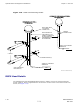
1X UBS Macro BTS FRU Figure 1-19 Optional RGPS Head Equipment Identication RGPS Head Equipment RGPS HEAD (MOTOROLA P/N STLN 6594) ALTERNATE RGP S HEAD (MOTOROLA P /N 0186012H04) 12-PIN DEUTSCH TYPE MMP CONNECTOR THREADED MOUNT ADAPTER THREADED MOUNT ADAPTER 12-PIN DEUTSCH TYPE MMP CONNECTOR ti-cdma-05702.
Optional RGPS Head Equipment Identication Chapter 1: Overview 1-52 68P09283A64-3 FOA SEP 2007
Chapter 2 Reference Procedures Performed At BTS Site ■ ■ ■ ■ ■ ■ ■ ■ ■ ■ ■ ■ ■ ■ ■ ■ ■ ■ ■ ■ ■ ■ ■ ■ ■ ■ ■ ■ ■ ■ ■ ■ ■ ■ ■ ■ ■ ■ ■ ■ ■ ■ ■ ■ ■ ■ ■ ■ ■ ■ ■ ■ ■ ■ ■ ■ ■ ■ ■ ■ ■ ■ ■ ■ ■ ■ 68P09283A64-3 SEP 2007 2-1 FOA
Reference Procedures Performed at BTS Site Chapter 2: Reference Procedures Performed At BTS Site Reference Procedures Performed at BTS Site ■ ■ ■ ■ ■ ■ ■ ■ ■ ■ ■ ■ ■ ■ ■ ■ ■ ■ ■ ■ ■ ■ ■ ■ ■ ■ ■ ■ ■ ■ ■ ■ ■ ■ ■ ■ ■ ■ ■ ■ ■ ■ ■ ■ ■ ■ ■ ■ ■ ■ ■ ■ ■ ■ ■ ■ ■ ■ ■ ■ ■ ■ ■ ■ Introduction The procedures in this chapter are referenced during various FRU replacement procedures and are performed by the technician at the BTS site.
1X UBS Macro BTS FRU Frame Power Down & Power-Up Procedures Frame Power Down & Power-Up Procedures ■ ■ ■ ■ ■ ■ ■ ■ ■ ■ ■ ■ ■ ■ ■ ■ ■ ■ ■ ■ ■ ■ ■ ■ ■ ■ ■ ■ ■ ■ ■ ■ ■ ■ ■ ■ ■ ■ ■ ■ ■ ■ ■ ■ ■ ■ ■ ■ ■ ■ ■ ■ ■ ■ ■ ■ ■ ■ ■ ■ ■ ■ ■ ■ Powering Down the Frame Prior to powering down the frame, perform the steps in Procedure 3-2 Shutdown site signaling functions procedure for a packet BTS on page 3-5 .
Frame Power Down & Power-Up Procedures Chapter 2: Reference Procedures Performed At BTS Site Procedure 2-2 Powering Up the Frame AT THE BTS SITE 1 For a +27 V DC powered UBS Macro frame, set the facility circuit breaker controlling external +27 V DC power to the frame to the ON position. For a — 48 V DC powered UBS Macro frame, set the facility circuit breaker controlling external 48 V DC power to the PSM to the ON position.
Chapter 3 Reference Procedures Performed At OMCR ■ ■ ■ ■ ■ ■ ■ ■ ■ ■ ■ ■ ■ ■ ■ ■ ■ ■ ■ ■ ■ ■ ■ ■ ■ ■ ■ ■ ■ ■ ■ ■ ■ ■ ■ ■ ■ ■ ■ ■ ■ ■ ■ ■ ■ ■ ■ ■ ■ ■ ■ ■ ■ ■ ■ ■ ■ ■ ■ ■ ■ ■ ■ ■ ■ ■ 68P09283A64-3 SEP 2007 3-1 FOA
Reference procedures performed at OMCR Chapter 3: Reference Procedures Performed At OMCR Reference procedures performed at OMCR ■ ■ ■ ■ ■ ■ ■ ■ ■ ■ ■ ■ ■ ■ ■ ■ ■ ■ ■ ■ ■ ■ ■ ■ ■ ■ ■ ■ ■ ■ ■ ■ ■ ■ ■ ■ ■ ■ ■ ■ ■ ■ ■ ■ ■ ■ ■ ■ ■ ■ ■ ■ ■ ■ ■ ■ ■ ■ ■ ■ ■ ■ ■ ■ Introduction The procedures in this chapter are referenced during various FRU replacement procedures and are performed by the OMCR operator.
1X UBS Macro BTS FRU Accessing OMCR CLI window Accessing OMCR CLI window ■ ■ ■ ■ ■ ■ ■ ■ ■ ■ ■ ■ ■ ■ ■ ■ ■ ■ ■ ■ ■ ■ ■ ■ ■ ■ ■ ■ ■ ■ ■ ■ ■ ■ ■ ■ ■ ■ ■ ■ ■ ■ ■ ■ ■ ■ ■ ■ ■ ■ ■ ■ ■ ■ ■ ■ ■ ■ ■ ■ ■ ■ ■ ■ Accessing OMCR CLI window Many of the FRU procedures require the OMCR operator to manipulate BTS logical devices. This is achieved using UNO or the OMCR (Operations and Maintenance Center - Radio) Command Line Interface (CLI).
Packet BTS shutdown procedures Chapter 3: Reference Procedures Performed At OMCR Packet BTS shutdown procedures ■ ■ ■ ■ ■ ■ ■ ■ ■ ■ ■ ■ ■ ■ ■ ■ ■ ■ ■ ■ ■ ■ ■ ■ ■ ■ ■ ■ ■ ■ ■ ■ ■ ■ ■ ■ ■ ■ ■ ■ ■ ■ ■ ■ ■ ■ ■ ■ ■ ■ ■ ■ ■ ■ ■ ■ ■ ■ ■ ■ ■ ■ ■ ■ Shutdown site signaling functions for a packet BTS If a complete site shutdown is required to support maintenance or upgrade operations, follow Procedure 3-2 to disable the packet BTS site.
1X UBS Macro BTS FRU Packet BTS shutdown procedures Procedure 3-2 Shutdown site signaling functions procedure for a packet BTS At the OMCR 1 Open a CLI window. Refer to Accessing OMCR CLI window on page 3-3. 2 • The recommended shutdown technique is to redirect subscribers to another site/carrier and then wait for any active calls to terminate before locking/disabling the BTS. • REDIRECT prevents future calls from being originated on the targeted resource.
Packet BTS shutdown procedures Procedure 3-2 (Continued) Chapter 3: Reference Procedures Performed At OMCR Shutdown site signaling functions procedure for a packet BTS 5 This step edits the REDIRECT parameters so that the Global Service Redirect Message to be broadcast on the paging channel redirects all subscribers away from the BTS and onto a different BTS or system.
1X UBS Macro BTS FRU Packet BTS shutdown procedures Procedure 3-2 Shutdown site signaling functions procedure for a packet BTS (Continued) 6 After all parameters are entered, the system displays the command to be sent and the prompt below. Verify the command syntax is correct. omc-000000>Accept [yes/no]? 7 At the prompt shown in step 6, enter Y to accept the command or N to go bottom and enter the correct value(s).
Packet BTS shutdown procedures Procedure 3-2 (Continued) Chapter 3: Reference Procedures Performed At OMCR Shutdown site signaling functions procedure for a packet BTS (Use the Network ID the subscriber units should expect to find on the system they are being redirected to.) expecting an integer number (from 0 to 2047) , . . . (A list of CDMA channels for neighbor sites that the subscriber units can use for redirection.
1X UBS Macro BTS FRU Packet BTS shutdown procedures Procedure 3-2 Shutdown site signaling functions procedure for a packet BTS (Continued) 19 The system prompts to enter each control parameter value one at a time. Skip through the prompts until reaching the following, and enter the parameter shown: ENABLE (This will force the Global Service Redirect Message to be broadcast on all of the sector paging channels at the BTS.
Packet BTS start-up procedures Chapter 3: Reference Procedures Performed At OMCR Packet BTS start-up procedures ■ ■ ■ ■ ■ ■ ■ ■ ■ ■ ■ ■ ■ ■ ■ ■ ■ ■ ■ ■ ■ ■ ■ ■ ■ ■ ■ ■ ■ ■ ■ ■ ■ ■ ■ ■ ■ ■ ■ ■ ■ ■ ■ ■ ■ ■ ■ ■ ■ ■ ■ ■ ■ ■ ■ ■ ■ ■ ■ ■ ■ ■ ■ ■ Restore site signaling operations for a packet BTS Restore site signaling operations according to Procedure 3-3.
1X UBS Macro BTS FRU Packet BTS start-up procedures Procedure 3-3 Restore site signaling operations procedure for a packet BTS (Continued) 8 This step edits the value of the Global Service Redirection Flag (GLOBALREDIRECT) in the congestion control parameters so that the Global Service Redirect Message is only broadcast on the sector paging channel when there is traffic congestion in the sector Enter the following command at the prompt using the applicable BTS number: omc-000000>EDIT BTS- CONGESTCON
Packet BTS start-up procedures Chapter 3: Reference Procedures Performed At OMCR Procedure 3-3 Restore site signaling operations procedure for a packet BTS (Continued) 15 In this step, use the values recorded in step 4 of Procedure 3-2 to answer the prompts for the EDIT BTS REDIRECT command, except for , enter 2.
Chapter 4 E-GPS (External-GPS) Replacement Procedures ■ ■ ■ ■ ■ ■ ■ ■ ■ ■ ■ ■ ■ ■ ■ ■ ■ ■ ■ ■ ■ ■ ■ ■ ■ ■ ■ ■ ■ ■ ■ ■ ■ ■ ■ ■ ■ ■ ■ ■ ■ ■ ■ ■ ■ ■ ■ ■ ■ ■ ■ ■ ■ ■ ■ ■ ■ ■ ■ ■ ■ ■ ■ ■ ■ ■ 68P09283A64-3 SEP 2007 4-1 FOA
E-GPS (External-GPS) Chapter 4: E-GPS (External-GPS) Replacement Procedures E-GPS (External-GPS) ■ ■ ■ ■ ■ ■ ■ ■ ■ ■ ■ ■ ■ ■ ■ ■ ■ ■ ■ ■ ■ ■ ■ ■ ■ ■ ■ ■ ■ ■ ■ ■ ■ ■ ■ ■ ■ ■ ■ ■ ■ ■ ■ ■ ■ ■ ■ ■ ■ ■ ■ ■ ■ ■ ■ ■ ■ ■ ■ ■ ■ ■ ■ ■ E-GPS Description The E-GPS is located in the UBS Macro BTS frame and is mounted at the very top of the frame. The E-GPS may be used instead of the optional Remote GPS (RGPS) head.
1X UBS Macro BTS FRU E-GPS (External-GPS) A failed E-GPS should be replaced immediately after failure detection and within the applicable MSO/QHSO backup time period (i.e., up to 8 hours MSO and up to 24 hours QHSO). After the replacement E-GPS is re-connected and powered up, it may take up to 30 minutes for the replacement E-GPS to successfully track and acquire satellites. Table 4-1 FRU Replacement Conditions FRU E-GPS Ref Designator E-GPS What to Shut Down...
E-GPS (External-GPS) Chapter 4: E-GPS (External-GPS) Replacement Procedures Prerequisite Before You Begin Before you begin, record the pertinent information in the following table (see Table 4-2): Table 4-2 Item Number Replacement List Item Number BTS number Failed E-GPS number E-GPS Replacement Procedure Perform the steps in Procedure 4-1to replace the E-GPS. Procedure 4-1 E-GPS Replacement Procedure AT THE BTS SITE 1 Disconnect all cables from the E-GPS front panel.
1X UBS Macro BTS FRU E-GPS (External-GPS) Optimization Required Consult the 1X UBS Macro BTS Optimization/ATP manual for the following optimization/test instructions: • Timing Initialization/Verification • BTS Device Database Audit • BTS Device Database Update 68P09283A64-3 SEP 2007 4-5 FOA
E-GPS (External-GPS) Chapter 4: E-GPS (External-GPS) Replacement Procedures 4-6 68P09283A64-3 FOA SEP 2007
Chapter 5 IDRF Replacement Procedure ■ ■ ■ ■ ■ ■ ■ ■ ■ ■ ■ ■ ■ ■ ■ ■ ■ ■ ■ ■ ■ ■ ■ ■ ■ ■ ■ ■ ■ ■ ■ ■ ■ ■ ■ ■ ■ ■ ■ ■ ■ ■ ■ ■ ■ ■ ■ ■ ■ ■ ■ ■ ■ ■ ■ ■ ■ ■ ■ ■ ■ ■ ■ ■ ■ ■ 68P09283A64-3 SEP 2007 5-1 FOA
IDRF (Integrated Duplexer RX Filter) Chapter 5: IDRF Replacement Procedure IDRF (Integrated Duplexer RX Filter) ■ ■ ■ ■ ■ ■ ■ ■ ■ ■ ■ ■ ■ ■ ■ ■ ■ ■ ■ ■ ■ ■ ■ ■ ■ ■ ■ ■ ■ ■ ■ ■ ■ ■ ■ ■ ■ ■ ■ ■ ■ ■ ■ ■ ■ ■ ■ ■ ■ ■ ■ ■ ■ ■ ■ ■ ■ ■ ■ ■ ■ ■ ■ ■ IDRF Description The IDRF is available in either the 800 MHz or 1.9 GHz RF band.
1X UBS Macro BTS FRU IDRF (Integrated Duplexer RX Filter) Table 5-1 IDRF Replacement Conditions FRU Ref Designator Integrated Duplexer RX Filter IDRF 1, 2, 3 (TX/RX main antenna & RX diversity; sectors 1, 2, 3) What to Shut Down... From the OMCR, lock all XMIs. Required Items Documents • 1X UBS Macro BTS Optimization/ATP manual. • T25 TORX bit • Torque driver • 19 mm open-end wrench (for N-type connectors) • SMA break over wrench - 1.
IDRF (Integrated Duplexer RX Filter) Chapter 5: IDRF Replacement Procedure Prerequisite Coordinate this repair task with the OMCR operator. Before You Begin Record the pertinent information in Table 5-2. Table 5-2 Item Number Replacement List Item Number BTS Failed IDRF number IDRF Replacement Procedure This procedure requires working on or around circuitry extremely sensitive to ESD. Wear a conductive, high impedance wrist strap during the procedure. Follow appropriate safety measures.
1X UBS Macro BTS FRU Procedure 5-1 IDRF (Integrated Duplexer RX Filter) Replacing an IDRF (Continued) The OMCR operator must lock all XMIs before the failed IDRF can be removed. 3 Lock each XMI by entering the following command at the prompt: omc-000000>LOCK XMI-- UNC 4 Display the status of each XMI, by entering the following command at the prompt: omc-000000>DISPLAY BTS- STATUS Verify that each XMI is in an OOS_MANUAL state.
IDRF (Integrated Duplexer RX Filter) Chapter 5: IDRF Replacement Procedure 5-6 68P09283A64-3 FOA SEP 2007
Chapter 6 SSI Replacement Procedures ■ ■ ■ ■ ■ ■ ■ ■ ■ ■ ■ ■ ■ ■ ■ ■ ■ ■ ■ ■ ■ ■ ■ ■ ■ ■ ■ ■ ■ ■ ■ ■ ■ ■ ■ ■ ■ ■ ■ ■ ■ ■ ■ ■ ■ ■ ■ ■ ■ ■ ■ ■ ■ ■ ■ ■ ■ ■ ■ ■ ■ ■ ■ ■ ■ ■ 68P09283A64-3 SEP 2007 6-1 FOA
SSI (Site Span I/O) Module Chapter 6: SSI Replacement Procedures SSI (Site Span I/O) Module ■ ■ ■ ■ ■ ■ ■ ■ ■ ■ ■ ■ ■ ■ ■ ■ ■ ■ ■ ■ ■ ■ ■ ■ ■ ■ ■ ■ ■ ■ ■ ■ ■ ■ ■ ■ ■ ■ ■ ■ ■ ■ ■ ■ ■ ■ ■ ■ ■ ■ ■ ■ ■ ■ ■ ■ ■ ■ ■ ■ ■ ■ ■ ■ SSI Description The first instance of the SSI is located in the right, front side of the IDRF shelf of the UBS Macro BTS Frame.
1X UBS Macro BTS FRU SSI (Site Span I/O) Module • E-GPS module I/O or RGPS head I/O or GPS Synch Sharing Input — RGPS 15-pin connector (DC operating power to the E-GPS module/RGPS head is provided via this connector). • Buffered BTS system time synchronize signal output for daisy chaining multiple frames at a BTS site to a common synchronization source — SYNC SHARING 15-pin connector. • External 10 MHz frequency reference input — EXT REF IN BNC connector.
SSI (Site Span I/O) Module Chapter 6: SSI Replacement Procedures SSI removal requires powering off the SSI and disconnecting all of its cables. Operation of the following will be interrupted: • E-GPS or RGPS whichever is applicable. • QHSO • ALARM/CONTROL for the optional PSM shelf • LMF • Customer alarm input/output devices • IP-packet backhaul The DMI controller will switchover to the DMI MSO as a backup reference source.
1X UBS Macro BTS FRU SSI (Site Span I/O) Module Table 6-2 ALARM LED State SSI LEDs States and Indications (Continued) INSTANCE LED State Indication STATUS LED State Flashing (1.5 sec-On/1 sec-Off) N/A N/A Partial (soft) FRU Failure N/A N/A Flashing (250 ms-On/250 ms-Off) FRU Booting up (not active) N/A N/A On FRU Active N/A Green Flashing (0.5 sec-On/0.5 sec-Off cycle count) followed by 3 sec-Off N/A Instance Indicator and No FRU Cabling Connection Errors Detected.
SSI (Site Span I/O) Module Chapter 6: SSI Replacement Procedures Prerequisite Coordinate this repair task with the OMCR operator. Before you begin Before you begin, enter the information into the following replacement list table. Table 6-3 Item Number Replacement List Item Number BTS number Failed SSI number SSI replacement procedure This procedure requires working on or around circuitry which is extremely sensitive to ESD. Wear a conductive, high impedance wrist strap during the procedure.
1X UBS Macro BTS FRU Procedure 6-1 SSI (Site Span I/O) Module Removing the failed SSI AT THE OMCR 1 Shut down site signaling functions according to Procedure 3-2 Shutdown site signaling functions procedure for a packet BTS on page 3-5. AT THE BTS SITE 2 Power down the SSI by setting the corresponding PDU SSI 20A circuit breaker to the off position (pulled out). Make sure the PDU SSI circuit breaker is set to OFF. You will be disconnecting multiple cables from connectors.
SSI (Site Span I/O) Module Procedure 6-2 Chapter 6: SSI Replacement Procedures Installing the replacement SSI (Continued) 3 Using a T25 TORX bit and torque driver, tighten the thumbscrews to 2.37 N-m (21 in-lb). 4 Reconnect all of the cables to the corresponding connectors on the SSI front panel. 5 Power up the SSI by setting the corresponding PDU SSI 20A circuit breaker to the on position (pushed in).
1X UBS Macro BTS FRU Unbalanced E1 Daughter Card Unbalanced E1 Daughter Card ■ ■ ■ ■ ■ ■ ■ ■ ■ ■ ■ ■ ■ ■ ■ ■ ■ ■ ■ ■ ■ ■ ■ ■ ■ ■ ■ ■ ■ ■ ■ ■ ■ ■ ■ ■ ■ ■ ■ ■ ■ ■ ■ ■ ■ ■ ■ ■ ■ ■ ■ ■ ■ ■ ■ ■ ■ ■ ■ ■ ■ ■ ■ ■ Unbalanced E1 Daughter Card Description The optional E1 daughter card is located on the front panel of the SSI. For E1 daughter card location and connector identification, refer to Figure 1-7 SSI front panel details on page 1-35 .
Unbalanced E1 Daughter Card Chapter 6: SSI Replacement Procedures Required items Documents • 1X UBS Macro BTS Optimization/ATP manual. • Torque driver • T20 TORX driver Tools Torque requirements • E1 daughter card mounting screws, 2.37 N-m (21 in-lb) Replacement unit • Unbalanced E1 daughter card (Motorola model STLN6327) Prerequisite Coordinate this repair task with the OMCR operator. Before you begin Before you begin, enter the information into the following replacement list table.
1X UBS Macro BTS FRU Unbalanced E1 Daughter Card E1 daughter card replacement procedure This procedure requires working on or around circuitry which is extremely sensitive to ESD. Wear a conductive, high impedance wrist strap during the procedure. Use appropriate safety measures. To replace the E1 daughter card perform the steps in Procedure 6-3.
Unbalanced E1 Daughter Card Chapter 6: SSI Replacement Procedures Procedure 6-3 Replacing the E1 daughter card (Continued) There is no optimization required for E1 daughter card replacement. AT THE OMCR 9 Restore site signaling operations according to Procedure 3-3 Restore site signaling operations procedure for a packet BTS on page 3-10.
1X UBS Macro BTS FRU QHSO (Quartz High Stability Oscillator) QHSO (Quartz High Stability Oscillator) ■ ■ ■ ■ ■ ■ ■ ■ ■ ■ ■ ■ ■ ■ ■ ■ ■ ■ ■ ■ ■ ■ ■ ■ ■ ■ ■ ■ ■ ■ ■ ■ ■ ■ ■ ■ ■ ■ ■ ■ ■ ■ ■ ■ ■ ■ ■ ■ ■ ■ ■ ■ ■ ■ ■ ■ ■ ■ ■ ■ ■ ■ ■ ■ QHSO Description The optional QHSO is located on the SSI rear panel (see Figure 1-8 SSI rear panel details on page 1-36).
QHSO (Quartz High Stability Oscillator) Chapter 6: SSI Replacement Procedures Table 6-6 FRU replacement conditions FRU Ref Designator QHSO HSO What to Shutdown... Nothing; FRU is hot swappable and BTS system timing is sourced by an alternate source. Required items Documents • 1X UBS Macro BTS Optimization/ATP manual. • Torque driver • T20 TORX driver • T25 TORX driver Tools Torque requirements • SSI mounting bracket thumbscrews and QHSO thumbscrew, 2.
1X UBS Macro BTS FRU QHSO (Quartz High Stability Oscillator) QHSO replacement procedure • This procedure requires working on or around circuitry extremely sensitive to ESD. Wear a conductive, high impedance wrist strap while performing this procedure. • Follow appropriate safety measures. Perform the steps described in Procedure 6-4 to replace the QHSO. Procedure 6-4 Replacing the QHSO AT THE BTS SITE 1 Wear a conductive, high impedance wrist strap while performing the following procedure.
QHSO (Quartz High Stability Oscillator) Chapter 6: SSI Replacement Procedures Procedure 6-4 Replacing the QHSO (Continued) 6 Grasp the left end (that is, thumbscrew end) of QHSO and pull it away from the SSI rear panel until the 9–pin D-connector is fully disengaged. 7 Slide the QHSO until its mounting tab is disengaged from the retaining slot on the SSI rear panel.
Chapter 7 XMI Replacement Procedures ■ ■ ■ ■ ■ ■ ■ ■ ■ ■ ■ ■ ■ ■ ■ ■ ■ ■ ■ ■ ■ ■ ■ ■ ■ ■ ■ ■ ■ ■ ■ ■ ■ ■ ■ ■ ■ ■ ■ ■ ■ ■ ■ ■ ■ ■ ■ ■ ■ ■ ■ ■ ■ ■ ■ ■ ■ ■ ■ ■ ■ ■ ■ ■ ■ ■ 68P09283A64-3 SEP 2007 7-1 FOA
XMI (Transceiver Module Internal) Module Chapter 7: XMI Replacement Procedures XMI (Transceiver Module Internal) Module ■ ■ ■ ■ ■ ■ ■ ■ ■ ■ ■ ■ ■ ■ ■ ■ ■ ■ ■ ■ ■ ■ ■ ■ ■ ■ ■ ■ ■ ■ ■ ■ ■ ■ ■ ■ ■ ■ ■ ■ ■ ■ ■ ■ ■ ■ ■ ■ ■ ■ ■ ■ ■ ■ ■ ■ ■ ■ ■ ■ ■ ■ ■ ■ XMI Description The XMI is available in either the 800 MHz or 1.9 GHz RF band. The XMI contains sector RF transceivers and integrated sector TX RF Linear Power Amplifiers (LPAs).
1X UBS Macro BTS FRU XMI (Transceiver Module Internal) Module The XMI has the following items: • Main XMI processor/memory. This processor communicates with the XPAC, RX and TX circuits, MMI and ENET (LMT) ports, and the controller in the DMI via the CPRI links. • Phase-locked loop (PLL) reference clock circuit that is synchronized to CPRI link serial data input from the DMI. This clock reference signal is used to frequency synthesize all RX & TX local oscillators.
XMI (Transceiver Module Internal) Module Chapter 7: XMI Replacement Procedures RX Main & RX Diversity Signal Handling In the UBS Macro frame, the main RX antenna signal from each sector IDRF (Integrated Duplexer RX Filter) is applied to the corresponding sector main RX RF input of XMI 1. This input is applied to the main receiver path of the corresponding XMI 1 sector receiver.
1X UBS Macro BTS FRU XMI (Transceiver Module Internal) Module XMI High-speed Serial data Links (HSL) The XMI has redundant 1.2288 Gbps high-speed serial data links, one link per HSL 1 and HSL 2 data ports on the front panel of the XMI. These data ports, on the XMI, are connected to the high-speed serial data interface on the DMIs. The high-speed serial data link has a multiplexed serial data signal that contains RX/TX sector-carrier traffic and overhead data as well as any DMI/XMI communications data.
XMI (Transceiver Module Internal) Module Chapter 7: XMI Replacement Procedures TX RF Small Signal Handling For 800 MHz XMIs, the TX RF small signal from each sector RF transmitter in the XMI is routed to the TXD connector on the front panel of the XMI. When the TXD connector is properly terminated, each sector TX RF path is completed and the TX RF small signal from each sector RF transmitter in the XMI is applied to the 3-sector TX RF input FTM.
1X UBS Macro BTS FRU XMI (Transceiver Module Internal) Module XPAC Functions The XMI PA Controller (XPAC) communicates with the XMI processor and controls/monitors the following XMI circuits: • 3-sector TX RF output FTM. • Three multi-carrier TX RF LPA sections; one LPA section for each sector. • Five cooling fans in the fan tray mounted on the rear of the XMI. The XPAC and the XMI processor exchange control data and status/alarm messages via a dedicated serial bus.
XMI (Transceiver Module Internal) Module Chapter 7: XMI Replacement Procedures Alarms will be reported during the replacement procedure. The XMI is not “hot swappable”. Table 7-1 FRU Replacement Conditions FRU XMI What to Shut Down... From the OMCR, lock the XMI being removed. Then shut down XMI DC input power. Required items Manpower • Two people are required to lift, carry, or handle the XMI module. Documents • 1X UBS Macro BTS Optimization/ATP manual. • T25 TORX bit. • Torque driver.
1X UBS Macro BTS FRU XMI (Transceiver Module Internal) Module XMI I/O Panel Connectors/Ports & LEDs XMI I/O Panel Figure 1-9 800 MHz XMI Module Front Panel I/O Detail on page 1-38 shows I/O connectors on the front panel of the UBS Macro BTS 800 MHz XMI. Figure 1-10 1.9 GHz XMI Module Front Panel I/O Detail on page 1-39 shows I/O connectors on the front panel of the UBS Macro BTS 1.9 GHz XMI. The top-to-bottom positioning of the XMI shown in these figures is the same as when it is installed in the frame.
XMI (Transceiver Module Internal) Module Chapter 7: XMI Replacement Procedures Connectors/Ports The following text describes each connector/port on the XMI front panel. • +27V & RTN - XMI DC input power connections. Connects to corresponding XMI DC power connector on the PDU of the UBS Macro frame. The PDU XMI DC power connector supplies protected +27 V via a 90 A circuit breaker. The +27V pin is the positive feed and RTN (i.e., DC ground) pin is the negative return.
1X UBS Macro BTS FRU XMI (Transceiver Module Internal) Module MMI and LMT ports are for debug purposes and are not intended for use by customer service personnel. • MMI - Debug RS-232 port allows the operator MMI access to the XMI MCU controller via a computer terminal through either a modem or a null modem cable. The MMI port is an 8-pin RJ-45 connector. • LMT - This port is intended for development use only.
XMI (Transceiver Module Internal) Module Chapter 7: XMI Replacement Procedures XMI “HOT" Warning Label Details The XMI has a “HOT" warning label attached to it (see Figure 7-1 for label location and indications). The hot warning label senses the surface temperature of the metal XMI housing. When the XMI surface temperature reaches 50 degrees C, the “HOT" warning is fully visible indicating that the XMI is too hot to touch and may cause burns.
1X UBS Macro BTS FRU XMI (Transceiver Module Internal) Module Prerequisites Do not touch the XMI with unprotected hands when the “HOT" label is fully visible. If the “HOT" label is fully visible, wear heat protective gloves when touching the metal case of the XMI. The “HOT" label becomes fully visible when the temperature of the metal case of the XMI reaches 50 degrees C. However, the label may be partially visible at lower case temperatures. The XMI module is heavy.
XMI (Transceiver Module Internal) Module Chapter 7: XMI Replacement Procedures Coordinate this repair task with the OMCR operator. Before You Begin Before you begin, record the pertinent information in the following table (see Table 7-3): Table 7-3 Item Number Replacement List Item Number BTS number XMI number XMI Replacement Procedures The XMI replacement procedures consist of removing the failed XMI and then installing the replacement XMI.
1X UBS Macro BTS FRU XMI (Transceiver Module Internal) Module Procedure 7-1 XMI Removal Procedure (Continued) 6 Lock the failed XMI by entering the following command at the prompt: omc-000000>LOCK XMI-- UNC 7 Display the status of the XMI, by entering the following command at the prompt: omc-000000>DISPLAY BTS- STATUS Verify that the failed XMI is in an OOS_MANUAL state. Go to step 8.
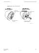
XMI (Transceiver Module Internal) Module Procedure 7-1 11 12 Chapter 7: XMI Replacement Procedures XMI Removal Procedure (Continued) Attach the removable XMI handle to the front of the failed XMI module (see Figure 1-9 800 MHz XMI Module Front Panel I/O Detail on page 1-38 or Figure 1-10 1.9 GHz XMI Module Front Panel I/O Detail on page 1-39 for location of XMI handle mounting screw holes) as follows: • Align handle screw holes with handle mounting screw holes on the XMI front panel.
1X UBS Macro BTS FRU Figure 7-2 attached) XMI (Transceiver Module Internal) Module Two People Properly Removing/Installing an XMI (removable XMI handle ti-cdma-06375.