XMI (Transceiver Module Internal) Module Chapter 7: XMI Replacement Procedures Figure 7-3 Two People Properly Carrying an XMI (removable XMI handle attached) ti-cdma-05891.
1X UBS Macro BTS FRU XMI (Transceiver Module Internal) Module XMI Installation Procedure Follow the steps in Procedure 7-2 to install the XMI. Procedure 7-2 XMI Installation Procedure AT THE BTS SITE The XMI module is heavy. Two people are required to lift, carry, or handle the XMI module. • Be sure the removable XMI handle is attached to the front of the XMI before physically handling the module. • Be sure two people use both hands and wear protective footwear when handling the XMI.
XMI (Transceiver Module Internal) Module Procedure 7-2 3 Chapter 7: XMI Replacement Procedures XMI Installation Procedure (Continued) This step requires two people. Perform the following: • (See Figure 7-3 Two People Properly Carrying an XMI (removable XMI handle attached) on page 7-18.) One person grasp the XMI by the handle with both hands. The second person grasp the XMI fan tray sides with both hands. Using safe lifting technique (i.e.
1X UBS Macro BTS FRU XMI (Transceiver Module Internal) Module Optimization Recommended Perform the following BTS Optimization/ATP procedures: • BTS Device Database Audit • BTS Device Database Update • TX Path Calibration Audit • Spectral Purity TX Mask ATP (optional) • Waveform Quality (Rho) ATP (optional) • Code Domain Power ATP (optional) • RSSI Test (FER Test is optional) Refer to the 1X UBS Macro BTS Optimization/ATP manual for the optimization procedures.
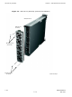
XMI Fan Tray Assembly Chapter 7: XMI Replacement Procedures XMI Fan Tray Assembly ■ ■ ■ ■ ■ ■ ■ ■ ■ ■ ■ ■ ■ ■ ■ ■ ■ ■ ■ ■ ■ ■ ■ ■ ■ ■ ■ ■ ■ ■ ■ ■ ■ ■ ■ ■ ■ ■ ■ ■ ■ ■ ■ ■ ■ ■ ■ ■ ■ ■ ■ ■ ■ ■ ■ ■ ■ ■ ■ ■ ■ ■ ■ ■ XMI Fan Tray Assembly Description The XMI fan tray assembly consists of five 27 V DC fans mounted in a housing. This housing is the removable rear panel of the XMI. (See Figure 7-4 and Figure 7-5.
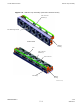
1X UBS Macro BTS FRU XMI Fan Tray Assembly Table 7-4 FRU Replacement Conditions FRU XMI fan tray assembly What to Shut Down... From the OMCR, lock the XMI being removed. Then shut down XMI DC input power. XMI Fan Tray Diagrams Figure 7-4 shows how the fan tray assembly is attached to the rear of the XMI. Figure 7-5 shows the fan tray assembly with five fans, built-in fan grille/finger-guards and five fan connector brackets with individual fan connectors and wiring.
XMI Fan Tray Assembly Chapter 7: XMI Replacement Procedures Figure 7-4 XMI Fan Tray Assembly (Removal & Installation) XMI (Rear View) XMI Fan Tray Assembly Mounting Screws (T20 Head) Mounting Screws T20 Head) ti-cdma-05918.
1X UBS Macro BTS FRU XMI Fan Tray Assembly Figure 7-5 XMI Fan Tray Assembly (External & Internal Views) Fan Connector Bracket (5) Fan Grille/Finger-Guard Internal View XMI Fan Housing Fan Fan Connector Bracket (5) Fan Connector Fan Wiring XMI Fan Housing ti-cdma-05919.
XMI Fan Tray Assembly Chapter 7: XMI Replacement Procedures Required Items Manpower • Two people are required to lift, carry, or handle the XMI module.
1X UBS Macro BTS FRU XMI Fan Tray Assembly The XMI should be locked by the OMCR operator just prior to removing the XMI or the XMI fan tray assembly. Coordinate this repair task with the OMCR operator. Before You Begin Before you begin, record the pertinent information in the following table (see Table 7-5): Table 7-5 Item Number Replacement List Item Number BTS number XMI number XMI Fan Tray Assembly Replacement Follow the steps in Procedure 7-3 to replace an XMI fan tray assembly.
XMI Fan Tray Assembly Chapter 7: XMI Replacement Procedures Procedure 7-3 XMI Fan Tray Assembly Replacement Procedure (Continued) the XMI fan tray assembly, go to Procedure 7-1 XMI Removal Procedure on page 7-14 and perform the steps starting at step 2, but stop after step step 8. Then return to step step 3 of this procedure. XMI fans must be completely stopped before removing the XMI fan tray assembly.
Chapter 8 DMI Replacement Procedures ■ ■ ■ ■ ■ ■ ■ ■ ■ ■ ■ ■ ■ ■ ■ ■ ■ ■ ■ ■ ■ ■ ■ ■ ■ ■ ■ ■ ■ ■ ■ ■ ■ ■ ■ ■ ■ ■ ■ ■ ■ ■ ■ ■ ■ ■ ■ ■ ■ ■ ■ ■ ■ ■ ■ ■ ■ ■ ■ ■ ■ ■ ■ ■ ■ ■ 68P09283A64-3 SEP 2007 8-1 FOA
DMI Replacement Procedures Chapter 8: DMI Replacement Procedures DMI Replacement Procedures ■ ■ ■ ■ ■ ■ ■ ■ ■ ■ ■ ■ ■ ■ ■ ■ ■ ■ ■ ■ ■ ■ ■ ■ ■ ■ ■ ■ ■ ■ ■ ■ ■ ■ ■ ■ ■ ■ ■ ■ ■ ■ ■ ■ ■ ■ ■ ■ ■ ■ ■ ■ ■ ■ ■ ■ ■ ■ ■ ■ ■ ■ ■ ■ Introduction This chapter includes FRU replacement procedures for the following: • DMI (Digital Module Internal) Assembly – This section covers the following: Preparing the replacement DMI assembly in the Field.
1X UBS Macro BTS FRU DMI (Digital Module Internal) Assembly DMI (Digital Module Internal) Assembly ■ ■ ■ ■ ■ ■ ■ ■ ■ ■ ■ ■ ■ ■ ■ ■ ■ ■ ■ ■ ■ ■ ■ ■ ■ ■ ■ ■ ■ ■ ■ ■ ■ ■ ■ ■ ■ ■ ■ ■ ■ ■ ■ ■ ■ ■ ■ ■ ■ ■ ■ ■ ■ ■ ■ ■ ■ ■ ■ ■ ■ ■ ■ ■ The R20 UBS Macro BTS only supports frame configurations with up to two DMIs and up to two XMIs. DMI Description The UBS Macro BTS frame must be equipped with at least one instance of the DMI. A second DMI is optional.
DMI (Digital Module Internal) Assembly Chapter 8: DMI Replacement Procedures The DMI assembly is the FRU (i.e., spare) that is used for DMI replacement. This assembly includes a chassis with a controller board, fans, front panel and two modem boards. This assembly does not include an outer housing. The DMI outer housing in the UBS Macro BTS frame is reused.
1X UBS Macro BTS FRU DMI (Digital Module Internal) Assembly System impact/considerations If the UBS Macro BTS frame is equipped with one DMI, then performing this replacement procedure will cause BTS downtime and suspend all call processing . If the UBS Macro BTS frame is equipped with two DMIs, then performing this replacement procedure for the Site Master DMI will temporarily cause BTS downtime. This is due to soft reset of the non-Site Master DMI during the DMI swap procedure.
DMI (Digital Module Internal) Assembly Chapter 8: DMI Replacement Procedures Tools • T20 TORX bit. • Torque driver. • ESD wrist straps. • ESD floor and bench top mats. • ESD containers. Replacement Units All models of DMI assemblies include: DMI chassis with controller board, fans and front panel. Factory built DMI assemblies: • DMI assembly with one 1X CDMA modem board (Motorola model STLN6681). • DMI assembly with one EV-DO modem board (Motorola model STLN6682).
1X UBS Macro BTS FRU DMI (Digital Module Internal) Assembly DMI I/O Panel Connectors/Ports & LEDs DMI I/O Panel Figure 1-11 DMI Module Front Panel Detail on page 1-41 shows I/O connectors on the front panel of the UBS Macro BTS DMI. The top-to-bottom positioning of the DMI shown in the figure is the same as when it is installed in the rack. This figure shows connector/port locations, connector types and brief cabling details.
DMI (Digital Module Internal) Assembly Chapter 8: DMI Replacement Procedures • RS232-1 and RS232-2 - Debug RS-232 ports allow MMI access to the DMI controller board via a computer terminal through either a modem or a null modem cable. These MMI ports are 8-pin RJ-45 connectors. • LMT and TEST - These ports are intended for development use only.
1X UBS Macro BTS FRU DMI (Digital Module Internal) Assembly Prerequisites ESD handling precautions must be adhered to when handling and working on the DMI assembly or the modem boards. Wear a conductive, high impedance wrist strap during handling. All work performed on the DMI assembly and modem boards must be done in an ESD protected work area. The procedures in this chapter requires working on or around circuitry that is extremely sensitive to ESD.
DMI (Digital Module Internal) Assembly Chapter 8: DMI Replacement Procedures DMI Preparation Area The DMI preparation area should provide the following ESD protection and the proper environmental conditions. • ESD Protection: Always wear a ground strap which must be connected to the electrostatic point on the equipment. Leave any conductive foam pieces on connectors or leads until the last moment. Remove these pieces just before installing the device.
1X UBS Macro BTS FRU Procedure 8-1 DMI (Digital Module Internal) Assembly Preparing the replacement DMI assembly in the Field AT THE OMCR 1 Ask the OMCR operator to get the EID information for the failed DMI by entering the following command at the prompt: omc-000000>DISPLAY BTS-- EID Observe the displayed response. Record the model number of the failed DMI and its modem board quantity and model numbers. Modem boards are designated as HDMODEM. Check values for both HDMODEM numbers (i.e.
DMI (Digital Module Internal) Assembly Chapter 8: DMI Replacement Procedures Procedure 8-1 Preparing the replacement DMI assembly in the Field (Continued) 7 If the failed DMI assembly to be replace is equipped with Modem 2, go to step 8 otherwise go to step 11. 8 Position the DMI assembly on its side with the front panel handle at the bottom (see Figure 8-2 Removing and installing Modem 2 on page 8-14). 9 Remove the modem board from its shipping packaging. Retain the packaging for later reuse.
1X UBS Macro BTS FRU DMI (Digital Module Internal) Assembly Figure 8-1 shows the DMI assembly with its bottom side up for access to Modem 1. Figure 8-1 Removing and installing Modem 1 Modem 1 7X Captive Screws Modem Connector Handle HD MEZZ Connector Controller Board Handle HD MEZZ Connector Front Panel ti-cdma-06168.
DMI (Digital Module Internal) Assembly Chapter 8: DMI Replacement Procedures Figure 8-2 shows the DMI assembly with its top side up for access to Modem 2. Figure 8-2 Removing and installing Modem 2 Modem 2 7X Captive Screws Modem Connector Handle HD MEZZ Connector Controller Board Front Panel HD MEZZ Connector Handle ti-cdma-06169.eps DMI Replacement Procedure Procedure 8-2 Replacing the DMI on page 8-15 includes: 1. Removing the failed DMI assembly from the UBS Macro BTS frame. 2.
1X UBS Macro BTS FRU DMI (Digital Module Internal) Assembly Procedure 8-2 Replacing the DMI AT THE OMCR 1 If you have not already asked the OMCR operator to get the EID information for the failed DMI, then have the OMCR operator enter the following command at the prompt: omc-000000>DISPLAY BTS-- EID Observe the displayed response. Record the model number of the failed DMI and its modem board quantity and model numbers. Modem boards are designated as HDMODEM.
DMI (Digital Module Internal) Assembly Chapter 8: DMI Replacement Procedures Procedure 8-2 Replacing the DMI (Continued) 11 Power down the failed DMI by setting the corresponding PDU DMI 20A circuit breaker to the off position (pulled out). Make sure the PDU DMI circuit breaker is set to OFF. You will be disconnecting multiple cables from connectors. If necessary, use masking tape and a marker and temporarily tag each cable as to the proper connector before disconnection.
1X UBS Macro BTS FRU DMI (Digital Module Internal) Assembly Procedure 8-2 Replacing the DMI (Continued) 18 Install the replacement DMI assembly, with modems, into the appropriate empty DMI housing in the UBS Macro BTS frame by performing the following: 1. Position the replacement DMI assembly on its bottom edge so that the front panel handle is on the right and the retaining fastener is at the top. 2. Pick up the replacement DMI assembly with two hands. 3.
DMI (Digital Module Internal) Assembly Chapter 8: DMI Replacement Procedures • BTS Device Database Audit • BTS Device Database Update • Timing Initialization/Verification • TX Path Calibration Audit • Spectral Purity TX Mask ATP (optional) • Waveform Quality (Rho) ATP (optional) • Code Domain Power ATP (optional) • FER Test • Alarm Verification Refer to the 1X UBS Macro BTS Optimization/ATP manual for the optimization procedures.
1X UBS Macro BTS FRU DMI (Digital Module Internal) Assembly Procedure 8-3 Dismantling the failed DMI assembly in the Field (Continued) 2 Remove Modem 1 from the failed DMI assembly by performing the following: 1. Use a T20 TORX bit/driver to completely loosen the seven captive screws that retain Modem 1 to the failed DMI assembly. 2. Grasp the modem connector handle with one hand and hold the assembly down with the other hand. 3.
Modem Boards Chapter 8: DMI Replacement Procedures Modem Boards ■ ■ ■ ■ ■ ■ ■ ■ ■ ■ ■ ■ ■ ■ ■ ■ ■ ■ ■ ■ ■ ■ ■ ■ ■ ■ ■ ■ ■ ■ ■ ■ ■ ■ ■ ■ ■ ■ ■ ■ ■ ■ ■ ■ ■ ■ ■ ■ ■ ■ ■ ■ ■ ■ ■ ■ ■ ■ ■ ■ ■ ■ ■ ■ The R20 UBS Macro BTS supports frame configurations with DMIs having up to two modem boards that can be either 1X CDMA modem, EV-DO modem, or one of each.
1X UBS Macro BTS FRU Modem Boards The modem replacement scenario is as follows: 1. Remove the affected DMI assembly from the DMI outer housing located in the UBS Macro BTS frame. 2. Replace Modem 1 or Modem 2, whichever is applicable, in the affected DMI assembly. 3. Install the affected DMI assembly equipped with the replacement modem into the DMI outer housing located in the UBS Macro BTS frame.
Modem Boards Chapter 8: DMI Replacement Procedures Required items Documents • 1X UBS Macro BTS Optimization/ATP manual. • T20 TORX bit. • Torque driver. • ESD wrist straps. • ESD floor and bench top mats. • ESD containers. Tools Replacement Units • CDMA 1X Modem Board (Motorola model SGLN6336). — OR — • EV-DO Modem Board (Motorola model SGLN6494). Prerequisites ESD handling precautions must be adhered to when handling and working on the DMI assembly or the modem boards.
1X UBS Macro BTS FRU Modem Boards Before You Begin Before you begin, record the pertinent information in the following table (see Table 8-5): Table 8-5 Item Number Replacement List Item Number BTS number DMI number Modem number Much of the modem board replacement procedure must be performed in a work area that meets the criteria described in DMI Preparation Area on page 8-10. Modem Board Replacement Procedure Procedure 8-4 Replacing a Modem Board on page 8-23 includes: 1.
Modem Boards Chapter 8: DMI Replacement Procedures Procedure 8-4 Replacing a Modem Board (Continued) 5 For an affected DMI that is the Site Master, go to step 6 For an affected DMI that is not the Site Master, go to step 7.
1X UBS Macro BTS FRU Modem Boards Procedure 8-4 Replacing a Modem Board (Continued) 15 ESD handling precautions must be adhered to when handling the DMI assembly. Place the affected DMI assembly into an ESD container. 16 Transport the affected DMI assembly in its ESD container and the needed replacement modem board in its ESD container to the DMI preparation area.
Modem Boards Chapter 8: DMI Replacement Procedures Procedure 8-4 Replacing a Modem Board (Continued) 22 Install the replacement modem board into Modem 1 position of the DMI assembly by performing the following: 1. Carefully place the front edge of Modem 1 under the lip of the DMI front panel. 2. Align the modem-to-controller connector halves so that they will mate together. 3. Press down firmly on the modem just above the modem-to-controller connector until the connector halves are fully seated. 4.
1X UBS Macro BTS FRU Modem Boards Procedure 8-4 Replacing a Modem Board (Continued) AT THE BTS SITE 28 ESD handling precautions must be adhered to when handling the DMI assembly. Plug the end of the ESD wrist strap into the UBS Macro BTS frame ESD jack This jack is located in the middle of the upper XMI shelf bracket. Attach the wrist strap to your wrist. 29 Remove the DMI assembly from the ESD container.
Modem Boards Chapter 8: DMI Replacement Procedures Figure 8-3 shows the DMI assembly with its bottom side up for access to Modem 1. Figure 8-3 Removing and installing Modem 1 Modem 1 7X Captive Screws Modem Connector Handle HD MEZZ Connector Controller Board Handle HD MEZZ Connector Front Panel ti-cdma-06168.
1X UBS Macro BTS FRU Modem Boards Figure 8-4 shows the DMI assembly with its top side up for access to Modem 2. Figure 8-4 Removing and installing Modem 2 Modem 2 7X Captive Screws Modem Connector Handle HD MEZZ Connector Controller Board Front Panel HD MEZZ Connector Handle ti-cdma-06169.
Modem Boards Chapter 8: DMI Replacement Procedures • BTS Device Database Audit • BTS Device Database Update • Timing Initialization/Verification • TX Path Calibration Audit • Spectral Purity TX Mask ATP (optional) • Waveform Quality (Rho) ATP (optional) • Code Domain Power ATP (optional) • FER Test • Alarm Verification Refer to the 1X UBS Macro BTS Optimization/ATP manual for the optimization procedures.
Chapter 9 PDU Replacement Procedures ■ ■ ■ ■ ■ ■ ■ ■ ■ ■ ■ ■ ■ ■ ■ ■ ■ ■ ■ ■ ■ ■ ■ ■ ■ ■ ■ ■ ■ ■ ■ ■ ■ ■ ■ ■ ■ ■ ■ ■ ■ ■ ■ ■ ■ ■ ■ ■ ■ ■ ■ ■ ■ ■ ■ ■ ■ ■ ■ ■ ■ ■ ■ ■ ■ ■ 68P09283A64-3 SEP 2007 9-1 FOA
Power Distribution Unit (PDU) Chapter 9: PDU Replacement Procedures Power Distribution Unit (PDU) ■ ■ ■ ■ ■ ■ ■ ■ ■ ■ ■ ■ ■ ■ ■ ■ ■ ■ ■ ■ ■ ■ ■ ■ ■ ■ ■ ■ ■ ■ ■ ■ ■ ■ ■ ■ ■ ■ ■ ■ ■ ■ ■ ■ ■ ■ ■ ■ ■ ■ ■ ■ ■ ■ ■ ■ ■ ■ ■ ■ ■ ■ ■ ■ PDU Description The PDU distributes +27 V DC output operating power to the UBS Macro BTS frame electronics. The PDU is located near the bottom of the UBS Macro BTS frame.
1X UBS Macro BTS FRU Power Distribution Unit (PDU) The PDU contains the following: • Internal DC input reverse polarity/over-voltage/surge protection, filtering, input/output bus bars. • Up to two DC input power cables/connectors for +27 V DC input to the rear of the PDU. • PDU front panel with cutouts for integrated circuit breaker and +27 V DC output power connectors.
Power Distribution Unit (PDU) Chapter 9: PDU Replacement Procedures Tools • 10 mm socket and ratchet • Torque driver • T25 TORX driver Torque requirements • PDU mounting screws; 4.77 N-m (42 in-lb) Replacement unit • PDU (Motorola model STPN4038) Prerequisites Coordinate this repair task with the OMCR operator. Before you begin Before you begin, record the pertinent information in Table 9-2.
1X UBS Macro BTS FRU Power Distribution Unit (PDU) To replace the PDU perform Procedure 9-1 and then Procedure 9-2. Procedure 9-1 Removing the failed PDU AT THE OMCR 1 Shut down site signaling functions according to Procedure 3-2 Shutdown site signaling functions procedure for a packet BTS on page 3-5. AT THE BTS SITE 2 Power down the UBS Macro BTS frame according to the section: Powering Down the Frame on page 2-3.
Power Distribution Unit (PDU) Procedure 9-2 Chapter 9: PDU Replacement Procedures Installing the replacement PDU AT THE BTS SITE 1 Properly position the replacement PDU in the rack location. Align the keyhole slots of the PDU mounting flanges with the two hanger screws and hang the replacement PDU on the rack. 2 Insert screws in the two open slots of the PDU rack mounting flanges. Tighten all four PDU rack mounting screws to 4.77 N-m (42 in-lb).
1X UBS Macro BTS FRU Breaker Module Assembly (BMA) Breaker Module Assembly (BMA) ■ ■ ■ ■ ■ ■ ■ ■ ■ ■ ■ ■ ■ ■ ■ ■ ■ ■ ■ ■ ■ ■ ■ ■ ■ ■ ■ ■ ■ ■ ■ ■ ■ ■ ■ ■ ■ ■ ■ ■ ■ ■ ■ ■ ■ ■ ■ ■ ■ ■ ■ ■ ■ ■ ■ ■ ■ ■ ■ ■ ■ ■ ■ ■ BMA Description The BMA is an integrated circuit breaker and output power connector. The circuit breaker provides current overload protection for the output power connector.
Breaker Module Assembly (BMA) Chapter 9: PDU Replacement Procedures Prior to replacing a BMA, the UBS Macro BTS site signaling is shutdown (i.e., disable the BTS site) then the UBS Macro BTS frame is powered down. Table 9-3 PDU Replacement Conditions FRU Breaker Module Assembly (BMA) Ref Designator What to Shutdown... XMI 1 – XMI 4, DMI 1 – DMI 5, SSI 1 – SSI 2, ACC 1 – ACC 2 Shutdown site signaling functions and then power down the frame.
1X UBS Macro BTS FRU Breaker Module Assembly (BMA) Prerequisites Coordinate this repair task with the OMCR operator. Before you begin Before you begin, record the pertinent information in Table 9-4. Table 9-4 Item number replacement list Item Number BTS number Failed BMA BMA replacement procedure BMA mounting screws must be tightened to the specied torque to prevent arcing and possible re hazard. To replace a BMA perform Procedure 9-3 and then Procedure 9-4.
Breaker Module Assembly (BMA) Chapter 9: PDU Replacement Procedures Procedure 9-3 Removing the failed BMA (Continued) Make sure the facility circuit breaker controlling external AC or DC power, whichever is applicable, to the UBS Macro BTS frame is set to the OFF position. You will be disconnecting multiple cables from connectors. If necessary, use masking tape and a marker and temporarily tag each cable as to the proper connector before disconnection.
1X UBS Macro BTS FRU Breaker Module Assembly (BMA) Procedure 9-4 Installing the replacement BMA (Continued) • Properly position the replacement BMA on the PDU output bus bars. • Align the BMA screw holes with the appropriate screw holes on the PDU output bus bars. • • 2 Insert the mounting screws. Using a TORX T25 driver, tighten all BMA mounting screws to 4.8 N-m (42.25 in-lb).
Breaker Module Assembly (BMA) Chapter 9: PDU Replacement Procedures Figure 9-1 PDU Front Panel Removal/Installation Detail PDU Front Panel Cover Latch Tab ti-cdma-06382.eps Figure 9-2 PDU Front Panel (cover removed) 2X 4X Mounting Screws 2X Mounting Screws Mounting Screws 2X Mounting Screws -0 V DC Bus Bar +27 V DC Bus Bar XMI 90A BMA DMI 20A BMA NOTE: 1. This diagram shows mounting details for each kind of BMA. It does not to show the exact BMA equipage.
Chapter 10 PSM Shelf Replacement Procedures ■ ■ ■ ■ ■ ■ ■ ■ ■ ■ ■ ■ ■ ■ ■ ■ ■ ■ ■ ■ ■ ■ ■ ■ ■ ■ ■ ■ ■ ■ ■ ■ ■ ■ ■ ■ ■ ■ ■ ■ ■ ■ ■ ■ ■ ■ ■ ■ ■ ■ ■ ■ ■ ■ ■ ■ ■ ■ ■ ■ ■ ■ ■ ■ ■ ■ 68P09283A64-3 SEP 2007 10-1 FOA
–48 V DC Power Supply Module (PSM) Shelf Chapter 10: PSM Shelf Replacement Procedures –48 V DC Power Supply Module (PSM) Shelf ■ ■ ■ ■ ■ ■ ■ ■ ■ ■ ■ ■ ■ ■ ■ ■ ■ ■ ■ ■ ■ ■ ■ ■ ■ ■ ■ ■ ■ ■ ■ ■ ■ ■ ■ ■ ■ ■ ■ ■ ■ ■ ■ ■ ■ ■ ■ ■ ■ ■ ■ ■ ■ ■ ■ ■ ■ ■ ■ ■ ■ ■ ■ ■ –48 V DC PSM Shelf Description The –48 V DC Power Supply Module (PSM) shelf is optional.
1X UBS Macro BTS FRU –48 V DC Power Supply Module (PSM) Shelf PSM shelf DC I/O interconnection Each PSM slot in the –48 V DC PSM shelf has two contacts (– feed and + return) for 48 V DC input and two contacts (+ feed and – return) for +27 V DC output. The –48 V DC PSM shelf has DC I/O bus bars at the rear of the shelf. The 48 V DC input contacts of the three PSM slots are parallel connected to the DC input bus bars.
–48 V DC Power Supply Module (PSM) Shelf Chapter 10: PSM Shelf Replacement Procedures Prior to replacing the –48 V DC PSM shelf, the UBS Macro BTS site signaling is shutdown (i.e., disable the BTS site) then the UBS Macro BTS frame is powered down. Table 10-1 –48 V DC PSM Shelf Replacement Conditions FRU –48 V DC Power Supply Module (PSM) shelf Ref Designator What to Shutdown... –48 V DC PSM shelf Shutdown site signaling functions and then power down the frame.
1X UBS Macro BTS FRU –48 V DC Power Supply Module (PSM) Shelf Before you begin Before you begin, record the pertinent information in Table 10-2. Table 10-2 Item number replacement list Item Number BTS number Failed –48 V DC PSM shelf number –48 V DC PSM shelf replacement procedure This procedure requires working on or around circuitry which is extremely sensitive to ESD. Wear a conductive, high impedance wrist strap during the procedure. Use appropriate safety measures.
–48 V DC Power Supply Module (PSM) Shelf Procedure 10-1 Chapter 10: PSM Shelf Replacement Procedures Removing the failed –48 V DC PSM shelf (Continued) 4 PSM weighs approximately 5 kg. Be careful when handling the PSM to prevent damage to the equipment and personal injury. Remove all the PSMs from the slots of the –48 V DC PSM shelf. Grasp the handle on the front panel of the PSM with one hand.
1X UBS Macro BTS FRU –48 V DC Power Supply Module (PSM) Shelf Procedure 10-2 Installing the replacement –48 V DC PSM shelf (Continued) 3 Reinstall all of the PSMs. Properly orient each PSM and insert it into the appropriate PSM shelf slot. Slowly slide the module into the shelf until the rear connectors are fully seated. Make sure that the PSM is fully engaged with the shelf backplane slot connectors. 4 Using a T25 TORX bit and torque driver, tighten the captive retaining thumbscrews of each PSM to 2.
220 V AC Power Supply Module (PSM) Shelf Chapter 10: PSM Shelf Replacement Procedures 220 V AC Power Supply Module (PSM) Shelf ■ ■ ■ ■ ■ ■ ■ ■ ■ ■ ■ ■ ■ ■ ■ ■ ■ ■ ■ ■ ■ ■ ■ ■ ■ ■ ■ ■ ■ ■ ■ ■ ■ ■ ■ ■ ■ ■ ■ ■ ■ ■ ■ ■ ■ ■ ■ ■ ■ ■ ■ ■ ■ ■ ■ ■ ■ ■ ■ ■ ■ ■ ■ ■ 220 V AC PSM Shelf Description The 220 V AC Power Supply Module (PSM) shelf is optional.
1X UBS Macro BTS FRU 220 V AC Power Supply Module (PSM) Shelf PSM shelf AC input interconnection Each PSM slot in the 220 V AC PSM shelf has a bulkhead connector. The 220 V AC line input pins from the bulkhead connector of the three PSM slots are parallel connected to the AC input buses. Each 220 V AC PSM has a rear panel AC input & status/alarm drawer connector that mates with a bulkhead connector in the PSM slot of the 220 V AC PSM shelf.
220 V AC Power Supply Module (PSM) Shelf Chapter 10: PSM Shelf Replacement Procedures PSM shelf alarm and control I/O interconnection Each PSM slot has a bulkhead connector. The status/alarm I/O signals of each of these slot connectors are interconnected to the ALARM & CONTROL connector on the front of the 220 V AC PSM shelf. Each 220 V AC PSM has a rear panel status/alarm drawer connector that mates with the bulkhead connector in the PSM slot of the PSM shelf.
1X UBS Macro BTS FRU 220 V AC Power Supply Module (PSM) Shelf Required items Documents • 1X UBS Macro BTS Optimization/ATP manual. • Torque driver • T25 TORX driver • T20 TORX bit with 12-inch extension • Flat blade screwdriver Tools Torque requirements • PSM shelf mounting screws; 4.77 N-m (42 in-lb) • PSM captive M4 retaining thumbscrew, 2.37 N-m (21 in-lb) • Terminal block cover box screws, 1.6 - 1.
220 V AC Power Supply Module (PSM) Shelf Chapter 10: PSM Shelf Replacement Procedures Before you begin Before you begin, record the pertinent information in Table 10-4. Table 10-4 Item number replacement list Item Number BTS number Failed 220 V AC PSM shelf number 220 V AC PSM shelf replacement procedure This procedure requires working on or around circuitry which is extremely sensitive to ESD. Wear a conductive, high impedance wrist strap during the procedure. Use appropriate safety measures.
1X UBS Macro BTS FRU 220 V AC Power Supply Module (PSM) Shelf Procedure 10-3 Removing the failed 220 V AC PSM shelf (Continued) 4 PSM weighs approximately 5 kg. Be careful when handling the PSM to prevent damage to the equipment and personal injury. Remove all the PSMs from the slots of the 220 V AC PSM shelf. Grasp the handle on the front panel of the PSM with one hand. Slowly pull the PSM out of the shelf slot while carefully supporting the bottom of the module with the other hand.
220 V AC Power Supply Module (PSM) Shelf Chapter 10: PSM Shelf Replacement Procedures Procedure 10-3 Removing the failed 220 V AC PSM shelf (Continued) 13 Using TORX T25 driver, completely loosen and remove the remaining rack mounting screws in the 220 V AC PSM shelf rack mounting flanges. 14 Grasp the 220 V AC PSM shelf and lift it up and off of the hanger screws. Pull the 220 V AC PSM shelf out of the rack and set it out of the way.
1X UBS Macro BTS FRU 220 V AC Power Supply Module (PSM) Shelf Procedure 10-4 Installing the replacement 220 V AC PSM shelf (Continued) 10 Using a flat blade screwdriver, turn the ground terminal screw counter clockwise (CCW) until the terminal is fully open. Insert the earth ground wire into the ground terminal. Turn the ground terminal screw clockwise (CW) to close the terminal and secure the wire. Tighten the terminal screw to 4.0 - 4.5 N-m (35 - 40 in-lb).
Power Supply Modules (PSMs) Chapter 10: PSM Shelf Replacement Procedures Power Supply Modules (PSMs) ■ ■ ■ ■ ■ ■ ■ ■ ■ ■ ■ ■ ■ ■ ■ ■ ■ ■ ■ ■ ■ ■ ■ ■ ■ ■ ■ ■ ■ ■ ■ ■ ■ ■ ■ ■ ■ ■ ■ ■ ■ ■ ■ ■ ■ ■ ■ ■ ■ ■ ■ ■ ■ ■ ■ ■ ■ ■ ■ ■ ■ ■ ■ ■ PSM Descriptions Up to three PSMs can be housed in the PSM shelf. A minimum of two PSMs are equipped for redundancy. An empty PSM 3 slot is covered with a filler panel.
1X UBS Macro BTS FRU Power Supply Modules (PSMs) –48 V DC PSM Description The –48 V DC PSM is a DC–DC converter. It operates from a nominal –48 V DC (–39 to –72 V) input and provides a 2700 W, +27 V DC (+/– 0.1 V) output. The output is designed to support load current sharing when configured for parallel output operation with other –48 V DC PSMs. The PSM has internal fans that circulate cooling air from the front to the rear of the module. Each –48 V DC PSM slides into a slot in the –48 V DC PSM shelf.
Power Supply Modules (PSMs) Chapter 10: PSM Shelf Replacement Procedures 220 V AC PSM Description The 220 V AC PSM is an AC–DC power supply. It contains AC line input filtering and AC–DC rectification. The rectifier output is applied to a DC–DC converter. The 220 V AC PSM operates from a nominal 220 V AC (154 to 300 V) input and provides a 2700 W, +27 V DC (+/– 0.1 V) output. The output is designed to support load current sharing when configured for parallel output operation with other 220 V AC PSMs.
1X UBS Macro BTS FRU Power Supply Modules (PSMs) PSM Front and Rear Panel Details –48 V DC PSM Front & Rear Panels Figure 10-1shows the –48 V DC PSM front and rear panel details. The figure below shows the PSM front and rear panels rotated 90 degrees Counter Clockwise (CCW) from when it is installed in the PSM shelf.
Power Supply Modules (PSMs) Chapter 10: PSM Shelf Replacement Procedures Figure 10-1 –48 V DC PSM Front & Rear Details Front Test Test Port (+) Red Port (-) LED Green LED Handle Captive M4 Retaining Thumbscrew Air Inlet Rear 48V DC Input 27V DC Output (+) Return (-) Feed (+) Feed (-) Return Status/Alarm Drawer Connector Air Outlet ti-cdma-05920.eps 220 V AC PSM Front & Rear Panels Figure 3-6 shows the 220 V AC PSM front and rear panel details.
1X UBS Macro BTS FRU Power Supply Modules (PSMs) The figure below shows the PSM front and rear panels rotated 90 degrees Counter Clockwise (CCW) from when it is installed in the PSM shelf.
Power Supply Modules (PSMs) Figure 10-2 Chapter 10: PSM Shelf Replacement Procedures 220 V AC PSM Front & Rear Details Front Test Test Port (+) Red Port (-) LED Green LED Handle Captive M4 Retaining Thumbscrew Air Inlet Rear 27V DC Output (+) Feed (-) Return Air Outlet AC Input and Status/Alarm Drawer Connector ti-cdma-05921.
1X UBS Macro BTS FRU Power Supply Modules (PSMs) Front Panel LEDs Two LEDs are on the front panel of each PSM with the following functionality: • A GREEN LED is displayed when the PSM is enabled and the output voltage is present. This LED remains on during a minor alarm condition. • A RED LED is displayed when a hard failure occurs (for example; a Fan failure or Converter failure).
Power Supply Modules (PSMs) Chapter 10: PSM Shelf Replacement Procedures Prerequisites Before you begin Before you begin, record the pertinent information in Table 10-6. Table 10-6 Item number replacement list Item Number BTS number Failed –48 V DC PSM number Failed 220 V AC PSM number PSM replacement procedure The PSM weighs approximately 5 kg. Be careful when handling the PSM to prevent damage to the equipment and personal injury.
1X UBS Macro BTS FRU Power Supply Modules (PSMs) Procedure 10-5 Replacing a PSM (Continued) 4 PSM weighs approximately 5 kg. Be careful when handling the PSM to prevent damage to the equipment and personal injury. Grasp the handle on the front panel of the PSM with one hand. Slowly pull the PSM out of the shelf slot while carefully supporting the bottom of the module with the other hand. 5 Properly orient the replacement PSM and insert it into the slot.
Power Supply Modules (PSMs) Chapter 10: PSM Shelf Replacement Procedures 10-26 68P09283A64-3 FOA SEP 2007
Chapter 11 RX Splitter Replacement Procedure ■ ■ ■ ■ ■ ■ ■ ■ ■ ■ ■ ■ ■ ■ ■ ■ ■ ■ ■ ■ ■ ■ ■ ■ ■ ■ ■ ■ ■ ■ ■ ■ ■ ■ ■ ■ ■ ■ ■ ■ ■ ■ ■ ■ ■ ■ ■ ■ ■ ■ ■ ■ ■ ■ ■ ■ ■ ■ ■ ■ ■ ■ ■ ■ ■ ■ 68P09283A64-3 SEP 2007 11-1 FOA
RX Splitter Chapter 11: RX Splitter Replacement Procedure RX Splitter ■ ■ ■ ■ ■ ■ ■ ■ ■ ■ ■ ■ ■ ■ ■ ■ ■ ■ ■ ■ ■ ■ ■ ■ ■ ■ ■ ■ ■ ■ ■ ■ ■ ■ ■ ■ ■ ■ ■ ■ ■ ■ ■ ■ ■ ■ ■ ■ ■ ■ ■ ■ ■ ■ ■ ■ ■ ■ ■ ■ ■ ■ ■ ■ RX Splitter Description The RX splitter is only used in UBS Macro BTS frames equipped with more than one XMI. The RX splitter used in the UBS Macro BTS frame is wide band and handles either 1.9 GHz or 800 MHz RX signals.
1X UBS Macro BTS FRU RX Splitter The RX splitter is not redundant. The following strategy is used during replacement of the RX splitter. When the RX splitter is disconnected/removed: • XMI 1 remains connected to the RX main RF antenna signal outputs for each sector, but has no connection to the RX diversity RF antenna signal outputs for each sector.
RX Splitter Chapter 11: RX Splitter Replacement Procedure Prerequisite Coordinate this repair task with the OMCR operator. Before you begin Before you begin, enter the information into the following replacement list table. Table 11-2 Item Number Replacement List Item Number BTS number Failed RX splitter number RX Splitter Replacement Procedure This procedure requires working on or around circuitry which is extremely sensitive to ESD.
1X UBS Macro BTS FRU RX Splitter Perform the steps in Procedure 11-1 to replace an RX splitter. Procedure 11-1 Replacing an RX Splitter AT THE BTS SITE 1 Wear a conductive, high impedance wrist strap. 2 Disconnect all cables from the front panel of the RX splitter and move them out of the way. 3 Using a T25 TORX driver, remove the two RX splitter mounting screws; one screw at each of the end mounting tabs on the front of the module.
RX Splitter Chapter 11: RX Splitter Replacement Procedure 11-6 68P09283A64-3 FOA SEP 2007
Chapter 12 RGPS Head Replacement Procedure ■ ■ ■ ■ ■ ■ ■ ■ ■ ■ ■ ■ ■ ■ ■ ■ ■ ■ ■ ■ ■ ■ ■ ■ ■ ■ ■ ■ ■ ■ ■ ■ ■ ■ ■ ■ ■ ■ ■ ■ ■ ■ ■ ■ ■ ■ ■ ■ ■ ■ ■ ■ ■ ■ ■ ■ ■ ■ ■ ■ ■ ■ ■ ■ ■ ■ 68P09283A64-3 SEP 2007 12-1 FOA
RGPS (Remote GPS) Head Chapter 12: RGPS Head Replacement Procedure RGPS (Remote GPS) Head ■ ■ ■ ■ ■ ■ ■ ■ ■ ■ ■ ■ ■ ■ ■ ■ ■ ■ ■ ■ ■ ■ ■ ■ ■ ■ ■ ■ ■ ■ ■ ■ ■ ■ ■ ■ ■ ■ ■ ■ ■ ■ ■ ■ ■ ■ ■ ■ ■ ■ ■ ■ ■ ■ ■ ■ ■ ■ ■ ■ ■ ■ ■ ■ RGPS Head Description The optional RGPS head is remotely located from the UBS Macro BTS frame. The RGPS head is typically mounted outside on a mast/pole. (See Figure 1-18 RGPS Head Mounting Details on page 1-50.
1X UBS Macro BTS FRU RGPS (Remote GPS) Head System Impact/Considerations Performing this replacement procedure should not require BTS downtime or impact call processing because of MSO or QHSO backup. However RGPS head downtime will occur. And alarms will be reported. A failed RGPS head should be replaced immediately after failure detection and within the applicable MSO/QHSO backup time period (i.e., up to 8 hours MSO and up to 24 hours QHSO).
RGPS (Remote GPS) Head Chapter 12: RGPS Head Replacement Procedure Replacement Unit • RGPS Head (Motorola model SLN6594), later version • RGPS Head (Motorola part number 0186012H04), earlier version If you need to replace the mounting hardware and/or the cable assembly with the RGPS head, contact your Motorola sales representative for the appropriate kits. Prerequisite Coordinate this repair task with the OMCR operator.
1X UBS Macro BTS FRU RGPS (Remote GPS) Head Procedure 12-1 RGPS Head Replacement Procedure (Continued) 3 Create slack in the RGPS cable so that 2 feet of cable can be extended out of the RGPS head end of the mounting pipe/conduit. 4 Loosen the pipe/conduit mounting hardware until the pipe/conduit is free to be unscrewed from the RGPS head. 5 To prevent twisting of cables, do not turn the RGPS head while holding the pipe/conduit.
RGPS (Remote GPS) Head Chapter 12: RGPS Head Replacement Procedure Procedure 12-1 RGPS Head Replacement Procedure (Continued) 11 Go to step step 16 12 Disconnect the RGPS cable from the RGPS head connector. It may be helpful to create some slack in the RGPS cable. The UBS Macro BTS frame automatically switches over to the backup reference source, QHSO/MSO, after disconnecting a working RGPS head. Alarm/event messages are also triggered.
1X UBS Macro BTS FRU RGPS (Remote GPS) Head Optimization Required Consult the 1X UBS Macro BTS Optimization/ATP manual for the following optimization/test instructions: • Timing Initialization/Verification 68P09283A64-3 12-7 FOA SEP 2007
Standard Printing Instructions Part Number 68P09283A64-3 Manual Title 1X UBS Macro BTS FRU Date SEP 2007 CSD/CND (US) Binder - 3 Slant D-ring binder - letter size 11.75in x 11.5in) white PVC. - Capacity depends on size of document. (no larger than 3 in) - Clear pockets on front and spine Printing - Cover / spine text overprinted onto Motorola cover stock. - Body printed double sided onto white letter size (8.5in x 11in) 70lb. Finishing - Shrink wrap contents.
Barcode 68P09283A64-3 -3 68P09283A64 SEP 2007 FOA