
Installation Instructions

Mid -capacit y Expansion Interconnect Cabling Chapter 3: Low -to -Mid Capacit y Fr ame Expansion Procedures
Required DMI to SSI cables
The required DMI to S SI cable is as follows:
• One DMI to S SI cable (Motorola part number 3088792T01)
DMI to SSI cabling procedure
P erform Procedure 3 -12 to install the DMI to S SI cable between S SI 1 and DMI 2.
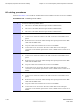
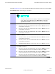
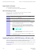
Procedure 3 -12 Installing DMI 2 to S SI 1 cable
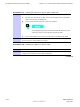
1
V erify that a DMI to S SI cable (Motorola part number 3088792T01) is already
installed/connected between DMI 1 front panel connector IDI/S SI 1 and S SI
1 front panel connector DMI 1/IDI .
2
Locate the following cables:
• One DMI to S SI cable (Motorola part number 3088792T01)
3
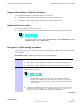
Install the DMI to S SI cable between DMI 2 and S SI 1 as follows:
1. Connect the appropriate end of the 3088792T01 cable to the IDI/S SI 1
connector on the DMI 2 front panel.
2. Route the loose end of the cable up above the XMI shelf DMI slot,
through the opening between the XMI shelf and the IDRF shelf , and
out the right side of the opening. Continue routing upwards along the
right rack rail and over in to S SI 1.
Excess cable should be coiled up and placed on top of the
XMI shelf top bracket.
3. Connect the loose end of the 3088792T01 cable to the DMI 2 connector
on the S SI 1 front panel.
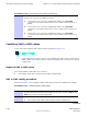
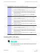
Installing RX splitter to XMI RX RF cables or RX share cable
Expansion to mid -capacity requires interconnection of RX RF signals between XMI 1 and XMI 2.
This can be accomplished by using an optional RX splitter or RX share cable.
If the optional RX splitter is used, locate the required RX splitter to XMI RX RF cables and then
perform Procedure 3 -13 .
If the optional RX splitter is not used, locate the required RX share cable and then perform
Procedure 3 -14 .
3 -30 68P09283A62 -3
PRELIMINARY A UG 2007