
Installation Instructions

Mid -capacit y Expansion Interconnect Cabling Chapter 3: Low -to -Mid Capacit y Fr ame Expansion Procedures
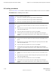
Procedure 3 -10 Connecting RX RF cables (Continued)
4
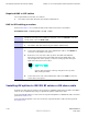
Connect the RX RF cables that were disconnected in step 3 to the bottom
panel of the second set of IDRFs as follows:
1. Connect the loose end of the 3088160T79 cable to the RX MAIN
connector on the bottom panel of the sector-1 IDRF of the second set of
IDRFs.
2. Connect the loose end of the 3088160T80 cable to the RX MAIN
connector on the bottom panel of the sector-2 IDRF of the second set of
IDRFs.
3. Connect the loose end of the 3088160T81 cable to the RX MAIN
connector on the bottom panel of the sector-3 IDRF of the second set of
IDRFs.
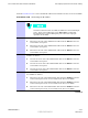
Installing XMI to DMI cables
Locate the required XMI to DMI cables and then perform Procedure 3 -11 .
F or the mid -capacity frame, there are four 3088791T02 cables used to interconnect
XMIs to DMIs. One of these cables is already installed/connected in the low -capacity
configuration.
Required XMI to DMI cables
The required XMI to DMI cables are as follows:
• Three XMI to DMI cables (Motorola part number 3088791T02)
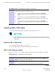
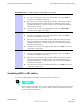
XMI to DMI cabling procedure
P erform Procedure 3 -11 to install the XMI to DMI cables between two XMIs and two DMIs.
Procedure 3 -11 Installing XMI to DMI cables
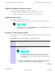
1
V erify that an XMI to DMI cable (Motorola part number 3088791T02) is
already installed/connected between XMI 1 front panel connector HSL 1 and
DMI 1 front panel connector XMI 1/BSI.
2
Locate the following cables:
• Three XMI to DMI cables (Motorola part number 3088791T02)
Continued
3 -28 68P09283A62 -3
PRELIMINARY A UG 2007