
Installation Instructions

R20 1X UBS Macro B T S Hardw are Installation Mid -capacit y Expansion Interconnect Cabling
P erform Procedure 3 -10 to connect the RX RF cables between XMI 2 and the second set of IDRFs.
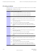
Procedure 3 -10 Connecting RX RF cables
On frames with more than one XMI, the XMIs have unused RX input
ports. These unused RX inputs ports
must not
be terminated.
T erminating these unused RX inputs ports will cause improper
operation of the XMIs.
1
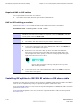
Disconnect the following RX RF cables from the front panel of XMI 1:
1. Disconnect the end of the 3088160T79 cable from the RX1 D connector
on the XMI 1 front panel.
2. Disconnect the end of the 3088160T80 cable from the RX2 D connector
on the XMI 1 front panel.
3. Disconnect the end of the 3088160T81 cable from the RX3 D connector
on the XMI 1 front panel.
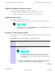
2
Connect the RX RF cables that were disconnected in step 1 to the front panel
of XMI 2 as follows:
1. Connect the loose end of the 3088160T79 cable to the RX1 D connector
on the XMI 2 front panel.
2. Connect the loose end of the 3088160T80 cable to the RX2 D connector
on the XMI 2 front panel.
3. Connect the loose end of the 3088160T81 cable to the RX3 D connector
on the XMI 2 front panel.
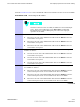
3
Disconnect the following RX RF cables from the bottom of the first (original)
set of IDRFs as follows:
1. Disconnect the end of the 3088160T79 cable from the RX DIV connector
on the bottom panel of the sector-1 IDRF of the first set of IDRFs.
2. Disconnect the end of the 3088160T80 cable from the RX DIV connector
on the bottom panel of the sector-2 IDRF of the first set of IDRFs.
3. Disconnect the end of the 3088160T81 cable from the RX DIV connector
on the bottom panel of the sector-3 IDRF of the first set of IDRFs.
Continued
68P09283A62 -3 3 -27
PRELIMINARY A UG 2007