
Installation Instructions

R20 1X UBS Macro B T S Hardw are Installation Mid -capacit y Expansion Interconnect Cabling
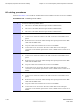
Procedure 3 -8 Installing the DMI 2 DC power cable (Continued)
3
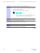
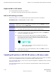
Route the loose end of the DMI DC power cable as follows:
1. Up the right side of the frame/rack and around to the back of the frame.
2. Through the opening between the XMI shelf and the IDRF shelf and over
the XMI shelf top bracket.
3. Down to the front panel of the appropriate DMI.
Excess cable should be coiled up and placed on top of the XMI
shelf top bracket.
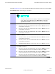
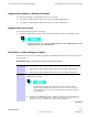
4
Connect the loose end of the DMI DC power cable to the +27 V DC input
power connector on the front panel of DMI 2.
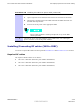
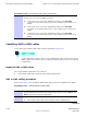
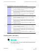
Installing/Connecting RF cables (XMI to IDRF)
Locate the required RF cables and then perform Procedure 3 -9 and Procedure 3 -10 as needed.
Required RF cables
The required TX RF cables are as follows:
• TX sector -1 RF cable (Motorola part number 3088160T73)
• TX sector -2 RF cable (Motorola part number 3088160T74)
• TX sector -3 RF cable (Motorola part number 3088160T75)
68P09283A62 -3 3 -25
PRELIMINARY A UG 2007