
Installation Instructions


R20 1X UBS Macro B T S Hardw are Installation Adding a DMI
Adding a DMI
■ ■ ■ ■ ■ ■ ■ ■ ■ ■ ■ ■ ■ ■ ■ ■ ■ ■ ■ ■ ■ ■ ■ ■ ■ ■ ■ ■ ■ ■ ■ ■ ■ ■ ■ ■ ■ ■ ■ ■ ■ ■ ■ ■ ■ ■ ■ ■ ■ ■ ■ ■ ■ ■ ■ ■ ■ ■ ■ ■ ■ ■
■
■
Objective
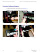
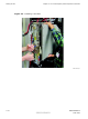
The objective of this section is to mount an additional DMI into the XMI shelf .
Cabling of the additional DMI will be performed after all of the additional expansion
equipment (i.e., XMI, circuit breaker/output power connector assemblies, etc.) that
connects to the additional DMI is installed in the frame.
Required items
Parts
The additional DMI is application dependent. Use one of the following factory built DMI
assemblies as applicable:
All models of DMI assemblies include: DMI chassis with controller board, fans and
front panel.
• DMI assembly with one 1X CDMA modem board (Motorola model STLN6681).
• DMI assembly with one EV -DO modem board (Motorola model STLN6682).
• DMI assembly with two 1X CDMA modem boards (Motorola model STLN6683).
• DMI assembly with one 1X CDMA modem board and one EV -DO modem board (Motorola
model STLN6684).
• DMI assembly with two EV -DO modem boards (Motorola model STLN6679).
68P09283A62 -3 3 -11
PRELIMINARY A UG 2007