
Installation Instructions

R20 1X UBS Macro B T S Hardw are Installation T ask 16: Connecting 220 V AC P ower
Procedure 2 -10 Procedure for T ask 16 (Continued)
1 1
Open the six line terminals as follows:
• Insert a flat blade screwdriver into each screw hole on top of the
terminal block.
• Turn the terminal screw CCW until the terminal is fully open..
F ailure to fully open the terminals can cause improper placement
of the insertion bridges in later steps.
12
Place an insertion bridge into the proper terminals. While holding the
bridge with one hand, turn the corresponding terminal screws CW until the
bridge is securely clamped.
13
Repeat step 12 for any remaining terminals requiring an insertion bridge.
14
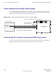
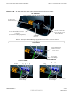
Connect the AC supply line wires to the proper terminals as follows:
• Insert a flat blade screwdriver into the appropriate screw hole on top
of the terminal block.
• Turn the terminal screw CCW until the terminal is fully open.
• Insert the appropriate wire into the terminal.
• While holding the wire with one hand, turn the corresponding terminal
screw CW until the wire is securely clamped. Tighten the terminal
screw to 4.0 - 4.5 N-m (35 - 40 in-lb).
Refer to Figure 2-24 as needed.
15
Repeat step 14 for any unconnected AC supply line wires.
16
V isually inspect all insertion bridge(s) and wires for proper placement. All
conductors must be inside the clamp of each terminal block.
17
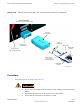
Place the cover box, with conduit attached, in position over the AC input
terminal block.
18
Insert the 4 screws to secure the cover box to the PSM shelf . Ensure that
the wires are not pinched.
19
Using a TORX T20 bit and driver , tighten the 4 screws to 1.6 - 1.8 N-m (14 -
16 in-lb).
20
Complete the installation of the AC wiring at the AC P ower source.
68P09283A62 -3 2 -69
A UG 2007 PRELIMINARY