
Installation Instructions

T ask 15: Connecting -48 V DC P ower Chapter 2: UBS Macro B T S Installation Procedure
Procedure 2 -9 Procedure for T ask 15
1
Ensure that the BTS ground cable (DD) is connected between the rack and
the Master Ground Bar (refer to T ask 3).
2
Ensure that the -48 V DC P ower Input Cable (CC) is NOT connected to the
main -48 V DC power source. Turn OFF the main -48 V DC power source.
3
Remove the components from the DC connector package.
4
Strip 35 mm of insulation from the negative (- V) and positive (+V) wires of
the power cable.
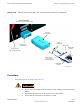
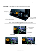
5
Place a DC contact/lug on the negative (- V) and positive (+V) wires of the
power cable. Refer to Figure 2-23 .
6
Using the appropriate crimping tool, crimp the DC contact/lug on to the
wires.
7
Observe the negative (- V) and positive (+V) wire polarities and insert the
DC contacts/lugs into the DC connector housing until a click sound is heard.
Refer to Figure 2-23 .
8
V erify the positive (+V) wire is installed in the positive position and the
negative (- V) wire is installed in the negative (-) position on the connector
housing.
9
Ensure that the wires are firmly fastened to the DC connector housing.
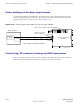
10
Tie the positive (+V) and negative (- V) wires of the cable together as shown
in Figure 2-22 .
1 1
Route the loose end of the -48 V DC P ower Input Cable (CC) to the site -48 V
DC source and connect the wires to the source.
12
V erify that proper polarity is maintained from the -48 V DC power source to
the UBS Macro BTS .
13
Use a Digital Multi-Meter (DMM) to measure the voltage
of the DC connector housing that was installed in step 7 .
P erform the following:
• Set the DMM to measure 48 V DC .
• Connect the DMM negative (GND/common) lead to the (-) terminal of
the cable connector .
• Connect the DMM positive lead to the (+) terminal of the cable
connector .
14
Turn on the main –48 V DC power source.
15
Observe the DMM and verify that the voltage is nominally +48 V (range =
+40 to +60 V).
16
Turn off the main –48 V DC power source.
17
Disconnect the DMM from the cable connector .
18
Connect -48 V DC P ower Input Cable (CC) connector to the -48 V DC input
power connector on the rear of the PSM shelf; blue connectors mate. Refer
to Figure 2-23 .
2 -64 68P09283A62 -3
PRELIMINARY A UG 2007