
Installation Instructions

T ask 15: Connecting -48 V DC P ower Chapter 2: UBS Macro B T S Installation Procedure
Power cabling and tie down requirements
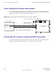
T o control the inductance at the BTS DC power input due to the spacing between wires used
in the -48 V DC P ower Input Cable (CC), the feed ( -V) and return (+V) wires must be bound
together at intervals of 1 meter or less. Refer to Figure 2 -22 .
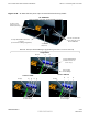
Figure 2 -22 48 V DC power input cable (CC) wire tie -wr ap example
ti-cdma-05695.eps
TIE ALL CABLES AT 1 METER INTERVALS
-48 V Power Source
BREAKER 1
-48 V DC
-48 V DC PSM SHELF
(Top View)
-48 V DC Power Input
Connector (BLUE)
+27 V DC Power Output Connector (ORANGE)
+0 V DC
+0 V DC
REAR
FRONT
-48 V DC
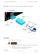
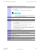
Contact/lug, DC connector housing and PDU input power
Figure 2 -23 shows the lugs and DC connector housing. This figure also shows the location at
which the -48 V DC Input P ower Cable (CC) connects to the rear of the PDU .
2 -62 68P09283A62 -3
PRELIMINARY A UG 2007