Task 4: Rack Mounting the Optional PSM Shelf Chapter 2: UBS Macro BTS Installation Procedure Task 4: Rack Mounting the Optional PSM Shelf ■ ■ ■ ■ ■ ■ ■ ■ ■ ■ ■ ■ ■ ■ ■ ■ ■ ■ ■ ■ ■ ■ ■ ■ ■ ■ ■ ■ ■ ■ ■ ■ ■ ■ ■ ■ ■ ■ ■ ■ ■ ■ ■ ■ ■ ■ ■ ■ ■ ■ ■ ■ ■ ■ ■ ■ ■ ■ ■ ■ ■ ■ ■ ■ Objectives The objectives of this procedure are as follows: • For -48 V DC or 220 V AC UBS only. Install the PSM shelf to the bottom of the rack.
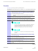
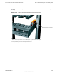
R20 1X UBS Macro BTS Hardware Installation Task 4: Rack Mounting the Optional PSM Shelf Procedure 2-3 Procedure for Task 4 (Continued) • 136 mm (5.35 inches) for PSM shelf 3 Partially insert an M5 x 12 mm screw into each location marked on the rack. Leave the screw heads extending 7 mm out from the rack surface. 4 Remove the PSM shelf from its packaging. 5 Align the keyhole slots in the PSM shelf with the bottom screws, installed in step 3 above (Refer to Figure 2-14).
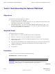
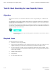
Task 4: Rack Mounting the Optional PSM Shelf Chapter 2: UBS Macro BTS Installation Procedure Procedural reference diagrams The following diagrams help clarify certain steps in Procedure 2-3. Figure 2-13 Hanger screw layout for the optional PSM shelf Hanger Screw Layout for optional PSM h Self 7 Hanger Screw (Detail A) Detail A Hanger Screw Extension 136 NOTE 1. All dimensions are in millimeters 2. 1800 mm high rack shown.
R20 1X UBS Macro BTS Hardware Installation Figure 2-14 Task 4: Rack Mounting the Optional PSM Shelf Hanging the PSM shelf PSM shelf keyhole located on hanger screw NOTE 1. Akeyhole/hanger screwis located on both the right and left sides. Bothkeyholes/hanger screws sho uld be engaged at the same time. 68P09283A62-3 ti-cdma-05869.
Task 5: Rack Mounting for Low-Capacity Frame Chapter 2: UBS Macro BTS Installation Procedure Task 5: Rack Mounting for Low-Capacity Frame ■ ■ ■ ■ ■ ■ ■ ■ ■ ■ ■ ■ ■ ■ ■ ■ ■ ■ ■ ■ ■ ■ ■ ■ ■ ■ ■ ■ ■ ■ ■ ■ ■ ■ ■ ■ ■ ■ ■ ■ ■ ■ ■ ■ ■ ■ ■ ■ ■ ■ ■ ■ ■ ■ ■ ■ ■ ■ ■ ■ ■ ■ ■ ■ Objective The objective of Task 5 is to install the UBS Macro carrier strip assembly into an EIA 19-inch rack.
R20 1X UBS Macro BTS Hardware Installation Task 5: Rack Mounting for Low-Capacity Frame Procedure Procedure 2-4 gives the procedure for performing Task 5. Procedure 2-4 Rack Mounting the Low-Capacity, +27 V DC UBS Macro BTS Assembly 1 Using a tape measure, measure mounting hanger screw location heights on each side of the rack (see Figure 2-15 Hanger screw layout for UBS Macro carrier strip assembly on page 2-39 ). Measure down from the very top of the rack. Mark the following screw locations: • 95.
Task 5: Rack Mounting for Low-Capacity Frame Chapter 2: UBS Macro BTS Installation Procedure Procedure 2-4 Rack Mounting the Low-Capacity, +27 V DC UBS Macro BTS Assembly (Continued) 8 Using a T25 TORX driver, tighten the four screws in carrier strip keyhole slots to 4.77 N-m (42 in-lb). 9 This step is optional and is only performed if there is a desire to remove the carrier strips from the frame.
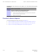
R20 1X UBS Macro BTS Hardware Installation Task 5: Rack Mounting for Low-Capacity Frame Figure 2-15 shows hanger screw layout used for mounting the UBS Macro carrier strip assembly onto a 1400 mm or 1800 mm high EIA 19-inch rack. Figure 2-15 Hanger screw layout for UBS Macro carrier strip assembly Hanger Screw Layout for UBS Carrier Strip Assembly 95.25 Hanger Screw (Detail A) 7 Detail A Hanger Screw Extension NOTE 1. All dimensions are in millimeters 2. 1800 mm high rack shown.
Task 5: Rack Mounting for Low-Capacity Frame Chapter 2: UBS Macro BTS Installation Procedure Figure 2-16 shows four people lifting and hanging the UBS Macro carrier strip assembly on the rack. Figure 2-16 UBS Macro BTS Handles Lifting and hanging the carrier strip assembly on the rack ti-cdma-06386.
R20 1X UBS Macro BTS Hardware Installation Task 5: Rack Mounting for Low-Capacity Frame Figure 2-17 shows the keyhole screw locations in a rack mounted UBS Macro carrier strip assembly. Figure 2-17 Carrier strip assembly keyhole screw locations Bottom keyhole of carrier strip located on hanger screw NOTE 1. Another carrier strip keyhole/hanger screw is loca ted at the top of the right side carrier strip/rack rail.
Task 6: Expanding the Low-capacity Frame Chapter 2: UBS Macro BTS Installation Procedure Task 6: Expanding the Low-capacity Frame ■ ■ ■ ■ ■ ■ ■ ■ ■ ■ ■ ■ ■ ■ ■ ■ ■ ■ ■ ■ ■ ■ ■ ■ ■ ■ ■ ■ ■ ■ ■ ■ ■ ■ ■ ■ ■ ■ ■ ■ ■ ■ ■ ■ ■ ■ ■ ■ ■ ■ ■ ■ ■ ■ ■ ■ ■ ■ ■ ■ ■ ■ ■ ■ If the initial UBS Macro BTS installation is for a low-capacity frame configuration, skip this task and go to Task 7: Cabling the Optional PSM Shelf on page 2-43.
R20 1X UBS Macro BTS Hardware Installation Task 7: Cabling the Optional PSM Shelf Task 7: Cabling the Optional PSM Shelf ■ ■ ■ ■ ■ ■ ■ ■ ■ ■ ■ ■ ■ ■ ■ ■ ■ ■ ■ ■ ■ ■ ■ ■ ■ ■ ■ ■ ■ ■ ■ ■ ■ ■ ■ ■ ■ ■ ■ ■ ■ ■ ■ ■ ■ ■ ■ ■ ■ ■ ■ ■ ■ ■ ■ ■ ■ ■ ■ ■ ■ ■ ■ ■ Objectives The objectives of this procedure are as follows: • For -48 V DC or 220 V AC UBS only.
Tasks 8-9: Connecting TX/RX Antennas Chapter 2: UBS Macro BTS Installation Procedure Tasks 8-9: Connecting TX/RX Antennas ■ ■ ■ ■ ■ ■ ■ ■ ■ ■ ■ ■ ■ ■ ■ ■ ■ ■ ■ ■ ■ ■ ■ ■ ■ ■ ■ ■ ■ ■ ■ ■ ■ ■ ■ ■ ■ ■ ■ ■ ■ ■ ■ ■ ■ ■ ■ ■ ■ ■ ■ ■ ■ ■ ■ ■ ■ ■ ■ ■ ■ ■ ■ ■ Objectives The objectives of performing Tasks 8-9 are as follows: • Install the external antenna cables to the Integrated Duplexer RX Filters (IDRFs). • Install terminators on the IDRFs.
R20 1X UBS Macro BTS Hardware Installation Tasks 8-9: Connecting TX/RX Antennas Procedure 2-6 Procedure for Tasks 8-9 (Continued) 2 Connect each antenna cable to the corresponding IDRF type N connector. Refer to Figure 2-1 or Figure 2-2, whichever is applicable, for the location of the UBS Macro BTS antenna connectors on the top of the IDRF. Using a 19 mm open–end hex wrench, tighten the cable connectors to 4.3 N-m (38 in-lb). The IDRFs are not labeled for a sector.
Tasks 10-13: Connecting RGPS, Spans, Customer Alarms Chapter 2: UBS Macro BTS Installation Procedure Tasks 10-13: Connecting RGPS, Spans, Customer Alarms ■ ■ ■ ■ ■ ■ ■ ■ ■ ■ ■ ■ ■ ■ ■ ■ ■ ■ ■ ■ ■ ■ ■ ■ ■ ■ ■ ■ ■ ■ ■ ■ ■ ■ ■ ■ ■ ■ ■ ■ ■ ■ ■ ■ ■ ■ ■ ■ ■ ■ ■ ■ ■ ■ ■ ■ ■ ■ ■ ■ ■ ■ ■ ■ Objectives The SSI provides only secondary surge protection for the RGPS and T1/E1 span connections.
R20 1X UBS Macro BTS Hardware Installation Tasks 10-13: Connecting RGPS, Spans, Customer Alarms Required items The following items are required: • Cable AA - Part number 3086433H12 • Cable W - Part number CGDS19797321 • Cable X - Part number CGDS19797321 All SSI cable connectors with jack-screws require a flat-blade driver and should be tightened to 1.02 N-m (9 in-lb).
Tasks 10-13: Connecting RGPS, Spans, Customer Alarms Chapter 2: UBS Macro BTS Installation Procedure For E1 unbalanced 75-Ohm BNC connector locations and labeling on the daughter card, refer to Figure 2-3 SSI front panel connectors on page 2-9. Table 2-11 also shows the correlation between spans and the E1 unbalanced Span I/O coaxial BNC connectors.
R20 1X UBS Macro BTS Hardware Installation Tasks 10-13: Connecting RGPS, Spans, Customer Alarms Table 2-11 T1/E1 I/O cable W (span) signal and pin information (Continued) Span number Signal name 7 8 T1/E1 Balanced Span 36-Cond Shielded Twisted Pair Cable (W) 37-Pin D-Sub Connector Pin Wire Color TX7_TIP 7 Red/Orange TX7_RING 26 Orange/Red RX7_TIP 18 Yellow/Green RX7_RING 36 Green/Yellow TX8_TIP 8 Red/Green TX8_RING 27 Green/Red RX8_TIP 19 Yellow/Brown RX8_RING 37 Brown/Yellow
Tasks 10-13: Connecting RGPS, Spans, Customer Alarms Chapter 2: UBS Macro BTS Installation Procedure Function ALARM connectors provide for Customer Defined Alarm Inputs and Outputs. The customer can connect BTS site alarm input sensors and output devices to the UBS Macro BTS, thus providing alarm reporting of active sensors as well as controlling output devices.
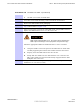
R20 1X UBS Macro BTS Hardware Installation Tasks 10-13: Connecting RGPS, Spans, Customer Alarms Figure 2-19 Customer alarm cable (X) pin numbering 19 LOOSE WIRES, NO CONNECTOR 37 37-Pin-Type (Male) 20 1 ti-cdma-05692.
Tasks 10-13: Connecting RGPS, Spans, Customer Alarms Chapter 2: UBS Macro BTS Installation Procedure Table 2-12 Customer alarm cable (X) pinout for customer IP 1-12 OP 1-4 (Continued) 37-Pin D-Sub Pin number Signal Description Wire Color 37Pin D-Sub Pin number Signal Description Wire Color 13 Customer Output NC 2 Black/Green 32 Customer Output NC 3 Brown/Black 14 Customer Output NO 3 Black/Brown 33 Customer Output Common 3 Gray/Black 15 Customer Output NO 4 Black/Gray 34 Customer Out
R20 1X UBS Macro BTS Hardware Installation Tasks 10-13: Connecting RGPS, Spans, Customer Alarms Table 2-13 Customer alarm cable (X) pinout for customer IP 13-24 OP 5-8 (Continued) 37-Pin D-Sub Pin number Signal Description 10 Not Connected 11 Customer Output NO 5 12 Wire Color 37-Pin D-Sub Pin number Signal Description Wire Color 29 Customer Output NC 5 Blue/Black Black/Blue 30 Customer Output Common 5 Orange/Black Customer Output NO 6 Black/Orange 31 Customer Output Common 6 Green/B
Tasks 10-13: Connecting RGPS, Spans, Customer Alarms Chapter 2: UBS Macro BTS Installation Procedure Procedure 2-7 Procedure for Tasks 10-13 (Continued) 4 Connect the 37-pin D-connector end of cable (W) to the SPAN connector on the front of the SSI. Refer to Figure 2-3 for the connector location on the SSI. 5 Route the loose end of cable (W) to the customer span line interconnect equipment and connect the wires. Refer to Table 2-11. The UBS Macro BTS currently supports only up to 4 spans.
R20 1X UBS Macro BTS Hardware Installation Task 14: Connecting +27 V DC Power Task 14: Connecting +27 V DC Power ■ ■ ■ ■ ■ ■ ■ ■ ■ ■ ■ ■ ■ ■ ■ ■ ■ ■ ■ ■ ■ ■ ■ ■ ■ ■ ■ ■ ■ ■ ■ ■ ■ ■ ■ ■ ■ ■ ■ ■ ■ ■ ■ ■ ■ ■ ■ ■ ■ ■ ■ ■ ■ ■ ■ ■ ■ ■ ■ ■ ■ ■ ■ ■ Objectives Task 14 is performed for +27 V DC UBS Macro BTS only.
Task 14: Connecting +27 V DC Power Chapter 2: UBS Macro BTS Installation Procedure Table 2-14 +27 V DC connector (Orange) parts information (Continued) Item Description Part Number Qty AWG 2/0 connector contact/lug Anderson Power Products Mfr Part# 907, or Allied Electronics Stk# 803-0500 2 per DC connector housing AWG 3/0 connector contact/lug Anderson Power Products Mfr Part# 916, or Allied Electronics Stk# 803-0502 2 per DC connector housing AWG 4/0 connector contact/lug Anderson Power Produc
R20 1X UBS Macro BTS Hardware Installation Task 14: Connecting +27 V DC Power Power cabling and tie down requirements To control the inductance at the BTS DC power input due to the spacing between wires used in the +27 V DC Power Input Cable (DC), the feed (+V) and return (-V) wires must be bound together at intervals of 1 meter or less. Refer to Figure 2-20.
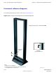
Task 14: Connecting +27 V DC Power Chapter 2: UBS Macro BTS Installation Procedure Figure 2-21 +27 V DC power input cable (DC) connector and connection to PDU PDU (rear view, shown partially cut away) Connector Housing (Orange) 2-Wire +27 VDC Power Cable (Customer Supplied) (-) BLACK WIRE (Typical) (+) (-) (+) +27 VDC Power Input (Orange) Crimp-on Contact/Lugs RED Wire (Typical) ti-cdma-05694.eps Cable Clamp Procedure Perform the Task 14 as given in Procedure 2-8.
R20 1X UBS Macro BTS Hardware Installation Task 14: Connecting +27 V DC Power Procedure 2-8 Procedure for Task 14 (Continued) 2 Ensure that the +27 V DC Power Input Cable (DC) is NOT connected to the main +27 V DC power source. Turn OFF the main +27 V DC power source. 3 Remove the components from the DC connector package. 4 Strip 35 mm of insulation from the negative (-V) and positive (+V) wires of the power cable.
Task 15: Connecting -48 V DC Power Chapter 2: UBS Macro BTS Installation Procedure Task 15: Connecting -48 V DC Power ■ ■ ■ ■ ■ ■ ■ ■ ■ ■ ■ ■ ■ ■ ■ ■ ■ ■ ■ ■ ■ ■ ■ ■ ■ ■ ■ ■ ■ ■ ■ ■ ■ ■ ■ ■ ■ ■ ■ ■ ■ ■ ■ ■ ■ ■ ■ ■ ■ ■ ■ ■ ■ ■ ■ ■ ■ ■ ■ ■ ■ ■ ■ ■ Objectives Task 15 is performed for -48 V DC UBS Macro BTS only. The objectives of this procedure are as follows: • Attaching the contact/lugs and connector on the -48 V DC power input cable wires.
R20 1X UBS Macro BTS Hardware Installation Task 15: Connecting -48 V DC Power Table 2-15 –48 V DC connector (Blue) parts information Item Description Part Number Qty Blue DC connector housing Anderson Power Products Mfr Part# 912, or Allied Electronics Stk# 803-0492 1 per –48 V DC power feed AWG 2/0 connector contact/lug Anderson Power Products Mfr Part# 907, or Allied Electronics Stk# 803-0500 2 per DC connector housing AWG 3/0 connector contact/lug Anderson Power Products Mfr Part# 916, or All
Task 15: Connecting -48 V DC Power Chapter 2: UBS Macro BTS Installation Procedure Power cabling and tie down requirements To control the inductance at the BTS DC power input due to the spacing between wires used in the -48 V DC Power Input Cable (CC), the feed (-V) and return (+V) wires must be bound together at intervals of 1 meter or less. Refer to Figure 2-22.
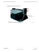
R20 1X UBS Macro BTS Hardware Installation Task 15: Connecting -48 V DC Power Figure 2-23 48 V DC power input cable (CC) connector and connection to PSM shelf -48 VDC PSM SHELF (rear view, shown partially cut away) Connector Housing (Blue) (+) -48 VDC Power Input (Blue) +27 VDC Power Output Cable (To PDU) Crimp-on Contact/Lugs Cable Clamp BLACK Wire (Typical) (-) (+) ??? 2-Wire -48 VDC Power Cable (Customer Supplied) BLUE Wire (Typical) (-) ti-cdma-05696.
Task 15: Connecting -48 V DC Power Procedure 2-9 Chapter 2: UBS Macro BTS Installation Procedure Procedure for Task 15 1 Ensure that the BTS ground cable (DD) is connected between the rack and the Master Ground Bar (refer to Task 3). 2 Ensure that the -48 V DC Power Input Cable (CC) is NOT connected to the main -48 V DC power source. Turn OFF the main -48 V DC power source. 3 Remove the components from the DC connector package.
R20 1X UBS Macro BTS Hardware Installation Task 16: Connecting 220 V AC Power Task 16: Connecting 220 V AC Power ■ ■ ■ ■ ■ ■ ■ ■ ■ ■ ■ ■ ■ ■ ■ ■ ■ ■ ■ ■ ■ ■ ■ ■ ■ ■ ■ ■ ■ ■ ■ ■ ■ ■ ■ ■ ■ ■ ■ ■ ■ ■ ■ ■ ■ ■ ■ ■ ■ ■ ■ ■ ■ ■ ■ ■ ■ ■ ■ ■ ■ ■ ■ ■ Objectives Task 16 is performed for 220 V AC UBS Macro BTS only. The objectives of this procedure are as follows: • Attaching customer supplied wiring and conduit for 220 V AC lines.
Task 16: Connecting 220 V AC Power Chapter 2: UBS Macro BTS Installation Procedure • Input AC cable sizing should be determined by Local Electrical Codes, using 90 C minimum rated conductors, and de–rating for 50 C operation. • The customer must provide a disconnect device and an over current protection device for the AC circuit supplying the UBS Macro BTS. A circuit breaker size of 30 Amperes is recommended, or as appropriate set by Local Electrical Code.
R20 1X UBS Macro BTS Hardware Installation Figure 2-24 Task 16: Connecting 220 V AC Power AC PSM shelf AC power input terminal block and wiring details AC PSM Shelf (rack mounted, rear view, shown partially cut away) +27 VDC Power Output Connector for Battery Backup 2 Screws On Each Side Secure Protective Cover Box To PSM Shelf AC Input Terminal Block Protective Cover Box (See Detail A for Wiring Configurations) Conduit/Wire Entry Hole Detail A - AC Input Terminal Wiring Configurations (protective co
Task 16: Connecting 220 V AC Power Chapter 2: UBS Macro BTS Installation Procedure Procedure Perform Task 16 as given in Procedure 2-10. • Do not wear a wrist strap while servicing the power supplies or power distribution cabling. • Ensure that the source for the AC power is in the OFF position. • Ensure that all of the PDU circuit breakers are OFF. Procedure 2-10 Procedure for Task 16 1 Set the source for the AC voltage to the OFF position.
R20 1X UBS Macro BTS Hardware Installation Task 16: Connecting 220 V AC Power Procedure 2-10 Procedure for Task 16 (Continued) 11 Open the six line terminals as follows: • Insert a flat blade screwdriver into each screw hole on top of the terminal block. • Turn the terminal screw CCW until the terminal is fully open.. Failure to fully open the terminals can cause improper placement of the insertion bridges in later steps. 12 Place an insertion bridge into the proper terminals.
Task 16: Connecting 220 V AC Power Chapter 2: UBS Macro BTS Installation Procedure 2-70 68P09283A62-3 PRELIMINARY AUG 2007
Chapter 3 Low-to-Mid Capacity Frame Expansion Procedures ■ ■ ■ ■ ■ ■ ■ ■ ■ ■ ■ ■ ■ ■ ■ ■ ■ ■ ■ ■ ■ ■ ■ ■ ■ ■ ■ ■ ■ ■ ■ ■ ■ ■ ■ ■ ■ ■ ■ ■ ■ ■ ■ ■ ■ ■ ■ ■ ■ ■ ■ ■ ■ ■ ■ ■ ■ ■ ■ ■ ■ ■ ■ ■ ■ ■ 68P09283A62-3 AUG 2007 3-1 PRELIMINARY
Low-to-Mid Capacity Frame Expansion Overview Chapter 3: Low-to-Mid Capacity Frame Expansion Procedures Low-to-Mid Capacity Frame Expansion Overview ■ ■ ■ ■ ■ ■ ■ ■ ■ ■ ■ ■ ■ ■ ■ ■ ■ ■ ■ ■ ■ ■ ■ ■ ■ ■ ■ ■ ■ ■ ■ ■ ■ ■ ■ ■ ■ ■ ■ ■ ■ ■ ■ ■ ■ ■ ■ ■ ■ ■ ■ ■ ■ ■ ■ ■ ■ ■ ■ ■ ■ ■ ■ ■ The R20 UBS Macro BTS supports single band 800 MHz or 1.9 GHz RF band, up to two XMIs, up to two DMIs and one SSI.
R20 1X UBS Macro BTS Hardware Installation Adding Circuit Breakers/Connectors to PDU Adding Circuit Breakers/Connectors to PDU ■ ■ ■ ■ ■ ■ ■ ■ ■ ■ ■ ■ ■ ■ ■ ■ ■ ■ ■ ■ ■ ■ ■ ■ ■ ■ ■ ■ ■ ■ ■ ■ ■ ■ ■ ■ ■ ■ ■ ■ ■ ■ ■ ■ ■ ■ ■ ■ ■ ■ ■ ■ ■ ■ ■ ■ ■ ■ ■ ■ ■ ■ ■ ■ Objective The objective of this section is to install additional circuit breaker/output power connector assemblies in the PDU.
Adding Circuit Breakers/Connectors to PDU Chapter 3: Low-to-Mid Capacity Frame Expansion Procedures Mounting screws are provided with each circuit breaker/output power connector assembly; four screws with the 90A assembly and two screws with the 20A assembly. • Side cutters; diagonal pliers or wire cutter • Small knife • TORX T25 bit and driver • Torque driver Procedure Procedure 3-1 contains the steps for adding a circuit breaker/output power connector assembly to the PDU.
R20 1X UBS Macro BTS Hardware Installation Adding Circuit Breakers/Connectors to PDU Procedure 3-1 Adding a Circuit Breaker/Output Power Connector Assembly to the PDU (Continued) 5 6 Position the circuit breaker/output power connector assembly as follows: • Circuit breaker actuator at the bottom and the DC output power connector at the top • Circuit breaker actuator facing toward the front of the frame • Align mounting screw holes of the circuit breaker/output power connector assembly with the corr
Adding Circuit Breakers/Connectors to PDU Chapter 3: Low-to-Mid Capacity Frame Expansion Procedures Procedural reference diagram The following diagram helps clarify certain steps in Procedure 3-1 . Figure 3-1 Adding a Breaker Assembly Module to the PDU A B C D 3-6 ti-cdma-06031.
R20 1X UBS Macro BTS Hardware Installation Adding an XMI Adding an XMI ■ ■ ■ ■ ■ ■ ■ ■ ■ ■ ■ ■ ■ ■ ■ ■ ■ ■ ■ ■ ■ ■ ■ ■ ■ ■ ■ ■ ■ ■ ■ ■ ■ ■ ■ ■ ■ ■ ■ ■ ■ ■ ■ ■ ■ ■ ■ ■ ■ ■ ■ ■ ■ ■ ■ ■ ■ ■ ■ ■ ■ ■ ■ ■ Objective The objective of this section is to mount an additional XMI into the XMI shelf. Cabling of the additional XMI will be performed after all of the additional expansion equipment (i.e.
Adding an XMI Chapter 3: Low-to-Mid Capacity Frame Expansion Procedures Tools The following tools are required: • TORX T25 bit and driver • Torque driver Procedure Procedure 3-2 contains the steps for adding a 2nd XMI to the XMI shelf. Procedure 3-2 Adding a 2nd XMI to the XMI Shelf The XMI module is heavy. Two people are required to lift, carry, or handle the XMI module. • Be sure the removable XMI handle is attached to the front of the XMI before physically handling the module.
R20 1X UBS Macro BTS Hardware Installation Adding an XMI Procedure 3-2 Adding a 2nd XMI to the XMI Shelf (Continued) 3 • One person grasp the XMI by the handle with both hands. The second person grasp the XMI fan tray sides with both hands. Using safe lifting technique (i.e. lift with your legs not your back), pick up the XMI and carry it over to the front of the frame.
Adding an XMI Figure 3-2 Chapter 3: Low-to-Mid Capacity Frame Expansion Procedures Installing a 2nd XMI ti-cdma-06375.
R20 1X UBS Macro BTS Hardware Installation Adding a DMI Adding a DMI ■ ■ ■ ■ ■ ■ ■ ■ ■ ■ ■ ■ ■ ■ ■ ■ ■ ■ ■ ■ ■ ■ ■ ■ ■ ■ ■ ■ ■ ■ ■ ■ ■ ■ ■ ■ ■ ■ ■ ■ ■ ■ ■ ■ ■ ■ ■ ■ ■ ■ ■ ■ ■ ■ ■ ■ ■ ■ ■ ■ ■ ■ ■ ■ Objective The objective of this section is to mount an additional DMI into the XMI shelf. Cabling of the additional DMI will be performed after all of the additional expansion equipment (i.e.
Adding a DMI Chapter 3: Low-to-Mid Capacity Frame Expansion Procedures Tools The following tools are required: • TORX T25 bit and driver • Torque driver • ESD wrist strap Prerequisite ESD handling precautions must be adhered to when handling the DMI assembly. Wear a conductive, high impedance wrist strap during handling. The procedures in this chapter requires working on or around circuitry that is extremely sensitive to ESD.
R20 1X UBS Macro BTS Hardware Installation Adding a DMI Procedure 3-3 Adding a 2nd DMI to the XMI Shelf (Continued) 2. Pick up the DMI assembly with two hands. 3. Insert the rear of the DMI assembly into the empty housing. 4. Slide the DMI assembly completely into the housing (see Figure 3-3 Installing a 2nd DMI on page 3-14. 5. Turn the retaining fastener CW (Clockwise) until finger tight to secure the DMI assembly in the housing.
Adding a DMI Chapter 3: Low-to-Mid Capacity Frame Expansion Procedures Procedural reference diagram The following diagram helps clarify certain steps in Procedure 3-3. Figure 3-3 Installing a 2nd DMI ti-cdma-06033.
R20 1X UBS Macro BTS Hardware Installation Adding a Second Set of IDRFs Adding a Second Set of IDRFs ■ ■ ■ ■ ■ ■ ■ ■ ■ ■ ■ ■ ■ ■ ■ ■ ■ ■ ■ ■ ■ ■ ■ ■ ■ ■ ■ ■ ■ ■ ■ ■ ■ ■ ■ ■ ■ ■ ■ ■ ■ ■ ■ ■ ■ ■ ■ ■ ■ ■ ■ ■ ■ ■ ■ ■ ■ ■ ■ ■ ■ ■ ■ ■ Objective The objective of this section is to mount a second set of IDRFs into the IDRF shelf.
Adding a Second Set of IDRFs Chapter 3: Low-to-Mid Capacity Frame Expansion Procedures Tools The following tools are required: • TORX T25 bit and driver • Torque driver Procedure Procedure 3-4 contains the steps for adding a second set of IDRFs to the IDRF shelf. Procedure 3-4 Adding a second set of IDRFs to the IDRF shelf 1 Remove the additional IDRFs from their packaging and inspect them for damage.
R20 1X UBS Macro BTS Hardware Installation Adding a Second Set of IDRFs Procedural reference diagram The following diagram helps clarify certain steps in Procedure 3-4. Figure 3-4 Installing the second set of IDRFs A B 68P09283A62-3 ti-cdma-06035.
Adding an Optional RX Splitter Chapter 3: Low-to-Mid Capacity Frame Expansion Procedures Adding an Optional RX Splitter ■ ■ ■ ■ ■ ■ ■ ■ ■ ■ ■ ■ ■ ■ ■ ■ ■ ■ ■ ■ ■ ■ ■ ■ ■ ■ ■ ■ ■ ■ ■ ■ ■ ■ ■ ■ ■ ■ ■ ■ ■ ■ ■ ■ ■ ■ ■ ■ ■ ■ ■ ■ ■ ■ ■ ■ ■ ■ ■ ■ ■ ■ ■ ■ Objective The objective of this section is to mount the optional RX splitter onto the bottom of the XMI shelf.
R20 1X UBS Macro BTS Hardware Installation Adding an Optional RX Splitter Procedure 3-5 Adding an RX splitter to the XMI shelf (Continued) • See Figure 3-5 Mounting the RX splitter on page 3-19. • Position the RX splitter as follows: RX splitter I/O connectors facing toward front of the frame. RX splitter mounting tabs, one on each end of splitter, facing up. In front of the XMI shelf bottom bracket.
Adding a third PSM (–48 V or 220 V AC only) Chapter 3: Low-to-Mid Capacity Frame Expansion Procedures Adding a third PSM (–48 V or 220 V AC only) ■ ■ ■ ■ ■ ■ ■ ■ ■ ■ ■ ■ ■ ■ ■ ■ ■ ■ ■ ■ ■ ■ ■ ■ ■ ■ ■ ■ ■ ■ ■ ■ ■ ■ ■ ■ ■ ■ ■ ■ ■ ■ ■ ■ ■ ■ ■ ■ ■ ■ ■ ■ ■ ■ ■ ■ ■ ■ ■ ■ ■ ■ ■ ■ A third PSM is required when expanding a –48 V DC or 220 VAC UBS Macro BTS frame from low capacity to mid capacity. The third PSM is for redundancy.
R20 1X UBS Macro BTS Hardware Installation Adding a third PSM (–48 V or 220 V AC only) Procedure Procedure 3-6 contains the steps for adding a third PSM to the PSM shelf. Procedure 3-6 Adding a 3rd PSM to the PSM shelf 1 Use a T25 TORX bit and driver to completely loosen the captive retaining thumbscrew on the filler plate that covers slot 3 of the PSM shelf. Remove the filler plate. 2 PSM weighs approximately 5 kg.
Mid-capacity Expansion Interconnect Cabling Chapter 3: Low-to-Mid Capacity Frame Expansion Procedures Mid-capacity Expansion Interconnect Cabling ■ ■ ■ ■ ■ ■ ■ ■ ■ ■ ■ ■ ■ ■ ■ ■ ■ ■ ■ ■ ■ ■ ■ ■ ■ ■ ■ ■ ■ ■ ■ ■ ■ ■ ■ ■ ■ ■ ■ ■ ■ ■ ■ ■ ■ ■ ■ ■ ■ ■ ■ ■ ■ ■ ■ ■ ■ ■ ■ ■ ■ ■ ■ ■ Remember – After all of the additional expansion equipment is installed and cabled, you must go to Task 7: Cabling the Optional PSM Shelf on page 2-43 of Chapter 2 UBS Macr
R20 1X UBS Macro BTS Hardware Installation Mid-capacity Expansion Interconnect Cabling DC power cabling procedures Procedure 3-7 Installing the XMI 2 DC power cable 1 Locate the XMI DC power cable (Motorola part number 3088319T03). 2 Connect the appropriate end of the XMI DC power cable to the +27 V DC input power connector on the top of XMI 2 front panel.
Mid-capacity Expansion Interconnect Cabling Chapter 3: Low-to-Mid Capacity Frame Expansion Procedures Procedure 3-7 Installing the XMI 2 DC power cable (Continued) 3 Route the loose end of the XMI DC power cable as follows: 1. Through the opening above XMI 2 between the XMI shelf and the IDRF shelf to the back of the XMI shelf. 2. Down and around the left side of the rear of XMI 2. To avoid blocking exhaust air from the XMI, the XMI DC power cable must not be routed directly behind the XMI. 3.
R20 1X UBS Macro BTS Hardware Installation Procedure 3-8 3 Mid-capacity Expansion Interconnect Cabling Installing the DMI 2 DC power cable (Continued) Route the loose end of the DMI DC power cable as follows: 1. Up the right side of the frame/rack and around to the back of the frame. 2. Through the opening between the XMI shelf and the IDRF shelf and over the XMI shelf top bracket. 3. Down to the front panel of the appropriate DMI.
Mid-capacity Expansion Interconnect Cabling Chapter 3: Low-to-Mid Capacity Frame Expansion Procedures RF cabling procedures Perform Procedure 3-9 to install the TX RF cables between XMI 2 and the second set of IDRFs.
R20 1X UBS Macro BTS Hardware Installation Mid-capacity Expansion Interconnect Cabling Perform Procedure 3-10 to connect the RX RF cables between XMI 2 and the second set of IDRFs. Procedure 3-10 Connecting RX RF cables On frames with more than one XMI, the XMIs have unused RX input ports. These unused RX inputs ports must not be terminated. Terminating these unused RX inputs ports will cause improper operation of the XMIs. 1 2 3 Disconnect the following RX RF cables from the front panel of XMI 1: 1.
Mid-capacity Expansion Interconnect Cabling Chapter 3: Low-to-Mid Capacity Frame Expansion Procedures Procedure 3-10 Connecting RX RF cables (Continued) 4 Connect the RX RF cables that were disconnected in step 3 to the bottom panel of the second set of IDRFs as follows: 1. Connect the loose end of the 3088160T79 cable to the RX MAIN connector on the bottom panel of the sector-1 IDRF of the second set of IDRFs. 2.
R20 1X UBS Macro BTS Hardware Installation Mid-capacity Expansion Interconnect Cabling Procedure 3-11 Installing XMI to DMI cables (Continued) 3 4 5 Install an XMI to DMI cable between XMI 1 and DMI 2 as follows: 1. Connect the appropriate end of the 3088791T02 cable to the HSL 2 connector on the XMI 1 front panel. 2. Route the loose end of the cable up above XMI 1, through the opening between the XMI shelf and IDRF shelf, and behind the hooks on the top XMI shelf bracket.
Mid-capacity Expansion Interconnect Cabling Chapter 3: Low-to-Mid Capacity Frame Expansion Procedures Required DMI to SSI cables The required DMI to SSI cable is as follows: • One DMI to SSI cable (Motorola part number 3088792T01) DMI to SSI cabling procedure Perform Procedure 3-12 to install the DMI to SSI cable between SSI 1 and DMI 2.
R20 1X UBS Macro BTS Hardware Installation Mid-capacity Expansion Interconnect Cabling Required RX splitter to XMI RX RF cables The required RX splitter to XMI RX RF cables are as follows: • RX splitter to XMI 1 RX RF cable (Motorola part number 3088407T10) • RX splitter to XMI 2 RX RF cable (Motorola part number 3088407T11) Required RX share cable The required RX share cable is as follows: • RX share cable (Motorola part number SGLN6345 which includes: 3088407T09 cable) The RX share cable connects
Mid-capacity Expansion Interconnect Cabling Chapter 3: Low-to-Mid Capacity Frame Expansion Procedures Procedure 3-13 Installing RX splitter to XMI RX RF cables (Continued) 3 2. Connect an XMI end connector to the RX EXP OUT connector on the XMI 1 front panel. 3. Connect the loose end of the same separate cable to the XMI 1 RX EXP IN connector on the RX splitter front panel. 4. Connect the remaining XMI end connector to the RX EXP IN connector on the XMI 1 front panel. 5.
R20 1X UBS Macro BTS Hardware Installation Mid-capacity Expansion Interconnect Cabling Procedure 3-14 Installing RX share cable (Continued) 1 Locate the following cable: • RX share cable (Motorola part number SGLN6345 which includes: 3088407T09 cable) The 3088407T09 cable contains two separate cables bundled together. The 3088407T09 cable has four ends with a connector on each end.
Mid-capacity Expansion Interconnect Cabling Chapter 3: Low-to-Mid Capacity Frame Expansion Procedures Procedure 3-14 Installing RX share cable (Continued) • The cable ends with the word OUT in its label must be connected to XMI connectors labeled RX EXP OUT. • The cable ends with the word IN in its label must be connected to XMI connectors labeled RX EXP IN.
Chapter 4 What’s Next ■ ■ ■ ■ ■ ■ ■ ■ ■ ■ ■ ■ ■ ■ ■ ■ ■ ■ ■ ■ ■ ■ ■ ■ ■ ■ ■ ■ ■ ■ ■ ■ ■ ■ ■ ■ ■ ■ ■ ■ ■ ■ ■ ■ ■ ■ ■ ■ ■ ■ ■ ■ ■ ■ ■ ■ ■ ■ ■ ■ ■ ■ ■ ■ ■ ■ 68P09283A62-3 AUG 2007 4-1 PRELIMINARY
Installation completion Chapter 4: What’s Next Installation completion ■ ■ ■ ■ ■ ■ ■ ■ ■ ■ ■ ■ ■ ■ ■ ■ ■ ■ ■ ■ ■ ■ ■ ■ ■ ■ ■ ■ ■ ■ ■ ■ ■ ■ ■ ■ ■ ■ ■ ■ ■ ■ ■ ■ ■ ■ ■ ■ ■ ■ ■ ■ ■ ■ ■ ■ ■ ■ ■ ■ ■ ■ ■ ■ At this point the hardware installation is complete. Perform the following tasks to complete the system installation.
R20 1X UBS Macro BTS Hardware Installation Installation completion Procedure 4-1 Cleaning the site (Continued) 6 Environment Perform the following to check the environment: • Check whether all covers, frame doors and fan housings are in place. • Confirm all power connections are tight. • Organize any items (such as manuals, materials, etc.) left on site and place them in a safe location specified by the site manager.
Installation completion Chapter 4: What’s Next Table 4-1 Installation completion checklist (Continued) Status No. Item 13 Cable racks properly grounded. 14 Static wrist straps are present. 15 Site cleaned, swept, and trash removed. 16 Any deficiencies reported to the appropriate people. 17 Correct polarity has been maintained from the DC power source to the frame. 18 Power has not been applied to any frame.