
User's Manual
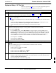


Transmit & Receive Antenna VSWR68P09258A31–A
Oct 2003
1X SCt 4812T BTS Optimization/ATP
I-5
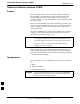
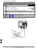
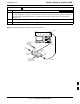
Figure I-2: Manual VSWR Test Setup Using HP8921 Test Set (800 MHz)
FWD (INCIDENT)
PORT 50–OHM
TERMINATED LOAD
RVS
(REFLECTED)
PORT
FEED LINE TO
ANTENNA
UNDER TEST
RF
SHORT
30 DB
DIRECTIONAL
COUPLER
OUTPUT
PORT
INPUT
PORT
FW00343
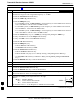
Equipment Setup – Advantest Test Set
Follow the steps in Table I-2 to set up test equipment required to
measure and calculate the VSWR for each antenna.
Table I-2: VSWR Measurement Procedure – Advantest Test Set
Step Action ADVANTEST
1 If you have not already done so, refer to the procedure in Table 3-5 on page 3-17 to set up test
equipment and interface the LMF computer to the BTS.
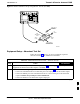
2 For manual VSWR testing using external directional coupler, refer to Figure I-3.
– Connect the communications test set RF OUT port to the input port of the directional coupler.
– Connect the INPUT port of the communication test set to the forward port on the directional
coupler. Terminate the forward port with a 50 Ohm load.
– Connect the RF short to the directional coupler output port.
. . . continued on next page
I