
User's Manual

Transmit & Receive Antenna VSWR
68P09258A31–A
Oct 2003
1X SCt 4812T BTS Optimization/ATP
I-4
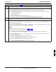
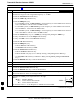
Table I-1: VSWR Measurement Procedure – HP Test Set
Step HP TEST SETAction
5 Calculate the VSWR per the equation shown to the right.
Where:
R
L(
dB) = P
A
(dBm) – P
S
(dBm)
P
A = Power reflected from antenna
P
S = Power reflected from short
A calculated value of –13.98 dB equates to VSWR of better than 1.5:1.
VSWR +
ȧ
ȧ
ȡ
Ȣ
1 ) 10
RL
20
1 – 10
RL
20
ȧ
ȧ
ȣ
Ȥ
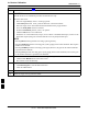
6 If the readings indicate a potential problem, verify the physical integrity of all cables (including any
in–line components, pads, etc.) and associated connections up to the antenna. If problem still persists,
consult antenna OEM documentation for additional performance verification tests or replacement
information.
7 Repeat steps 2 through 6 for all remaining TX sectors/antennas.
8 Repeat steps 2 through 6 for all remaining RX sectors/antennas.
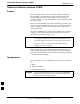
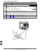
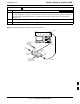
Figure I-1: Manual VSWR Test Setup Using HP8921 Test Set (1700/1900 MHz)
RF OUT
ONLY
PORT
RF
IN/OUT
PORT
RVS
(REFLECTED)
PORT
FEED LINE TO
ANTENNA
UNDER TEST
RF SHORT
30 DB
DIRECTIONAL
COUPLER
OUTPUT
PORT
FWD (INCIDENT)
PORT 50–OHM
TERMINATED LOAD
INPUT
PORT
FW00342
I