
User's Manual

Power Delta Calibration
68P09258A31–A
Oct 2003
1X SCt 4812T BTS Optimization/ATP
H-10
Agilent E4406A Power Delta Calibration
The Agilent E4406A transmitter tester and E4432B signal generator test
equipment combination can be used for ISC of IS–2000 CDMA 1X as
well as IS–95A/B operation modes. The power delta calibration is
performed on the E4406A, but the E4432B is required to generate the
reference signal used to calculate the power delta offset. After the offset
value has been calculated, add it to the TX cable loss value in the LMF.
Follow the procedure in Table H-4 to perform the Agilent E4406A
Power Delta Calibration procedure.
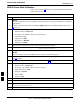
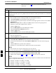
Table H-4: Agilent E4406A Power Delta Calibration Procedure
Step Action
NOTE
Perform this procedure after test equipment has been allowed to warm–up and stabilize for a minimum
of 60 minutes. After it is warmed up and stabilized, calibrate the test equipment as described in the
“Test Set Calibration” section of the Optimization/Calibration chapter in the SC 4812T
Optimization/ATP manual.
1 Zero the Power Meter prior to connecting the power sensor to the RF cable from the signal generator.
NOTE
For best accuracy, always re–zero the power meter before connecting the power sensor to the
component being calibrated.
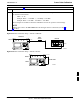
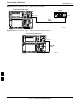
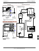
2 Connect a short RF cable from the E4432B RF OUTPUT connector the HP437 power meter power
sensor (see Figure H-7).
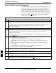
3 Set the E4432B signal generator as follows:
– Press Preset to exit any modes for which the signal generator is configured.
– Press Frequency and enter the frequency of the channel to be calibrated using the numeric
keypad.
– Using the soft keys to the right of the screen, select the frequency range to be measured (for
example, MHz).
– Press Amplitude and, using the numeric keypad, set signal amplitude to 0 (zero).
– Using the soft keys, set the measurement type to dBm.
4 On the E4432B, press RF On/Off to toggle the RF output to RF ON.
– Note that the RF On/Off status in the screen display changes.
5 Measure and record the value reading on the HP437 power meter as result A____________________.
6 On the E4432B, press RF On/Off to toggle the RF output to RF OFF.
– Note that the RF On/Off status in the screen display changes.
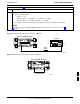
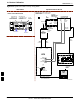
7 Disconnect the short RF cable from the HP437 power meter power sensor, and connect it to the
RF INPUT connector on the E4406A transmitter tester (see Figure H-8).
. . . continued on next page
H