
User's Manual

Test Equipment Set-up
68P09258A31–A
Oct 2003
1X SCt 4812T BTS Optimization/ATP
F-24
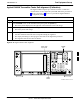
Calibrating Test Cable Setup using Advantest R3465
NOTE
Be sure the GPIB Interface is OFF for this procedure.
Perform the procedure in Table F-16 to calibrate the test cable setup
using the Advantest R3465. Advantest R3465 Manual Test setup and
calibration must be performed at both the TX and RX frequencies.
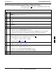
Table F-16: Procedure for Calibrating Test Cable Setup Using Advantest R3465
Step Action
NOTE
– This procedure can only be performed after test equipment has been allowed to warm–up and
stabilize for a minimum of 60 minutes.
1 Press the SHIFT and the PRESET keys located below the display.
2 Press the ADVANCE key in the MEASUREMENT area of the control panel.
3 Select the CDMA Sig CRT menu key.
4 Select the Setup CRT menu key.
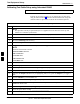
5 Using the vernier knob and the cursor keys set the following parameters:
NOTE
Fields not listed remain at default.
Generator Mode: SIGNAL
Link: FORWARD
Level Unit: dBm
CalCorrection: ON
Level Offset: OFF
6 Select the return CRT menu key.
7 Press FREQ key in the ENTRY area.
8 Set the frequency to the desired value using the keypad entry keys.
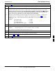
9 Verify that the Mod CRT menu key is highlighting OFF; if not, press the Mod key to toggle it OFF.
10 Verify that the Output CRT menu key is highlighting OFF; if not, press the Output key to toggle it
OFF.
11 Press the LEVEL key in the ENTRY area.
12 Set the LEVEL to 0 dBm using the key pad entry keys.
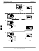
13 Zero power meter. Next connect the power sensor directly to the “RF OUT” port on the R3561L
CDMA Test Source Unit.
14 Press the Output CRT menu key to toggle Output to ON.
15 Record the power meter reading ________________________
16 Disconnect the power meter sensor from the R3561L RF OUT jack.
. . . continued on next page
F