
User's Manual


Test Equipment Set-up68P09258A31–A
Oct 2003
1X SCt 4812T BTS Optimization/ATP
F-23
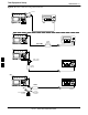
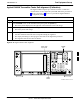
HP PCS Interface Test Equipment Setup for Manual Testing
Follow the procedure in Table F-15 to setup the HP PCS Interface Box
for manual testing.
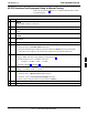
Table F-15: HP PCS Interface Test Equipment Setup for Manual Testing
n Step Action
NOTE
Verify GPIB controller is turned off.
1 Insert HP83236B Manual Control/System card into the memory card slot.
2 Under Screen Controls, press the [TESTS] push-button to display the TESTS (Main Menu)
screen.
3 Position the cursor at Select Procedure Location and select. In the Choices selection box, select
CARD.
4 Position the cursor at Select Procedure Filename and select. In the Choices selection box, select
MANUAL.
5 Position the cursor at RUN TEST and select OR press the K1 push-button.
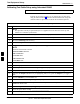
6 Set channel number=<chan#>:
– Position cursor at Channel Number and select.
– Enter the chan# using the numeric keypad and then press [Enter] (the screen will blank).
– When the screen reappears, the chan# will be displayed on the channel number line.
NOTE
If using a TMPC with Tower Top Amplifier (TTA) skip Step 7.
7
S Set RF Generator level= –119 dBm + Cal factor
Example: –119 dBm + 2 dB = –117 dBm
S Continue with Step 9 (skip Step 8).
8 Set RF Generator level= –116 dBm + Cal factor.
Example: –116 dBm + 2 dB = –114 dBm
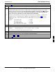
9 Set the user fixed Attenuation Setting to 0 dB:
– Position cursor at RF Generator Level and select.
– Position cursor at User Fixed Atten Settings and select.
– Enter 0 (zero) using the numeric keypad and press [Enter].
10 Select Back to Previous Menu.
11 Select Quit, then select Yes.
F