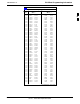
PN Offset Programming Information 68P09258A31–A Table B-1: PnMask I and PnMask Q Values for PilotPn Pilot PN 401 402 403 404 405 406 407 408 409 410 411 412 413 414 415 416 417 418 419 420 421 422 423 424 425 426 427 428 429 430 431 432 433 434 435 436 437 438 439 440 441 442 443 444 445 446 447 448 449 450 I 14–Chip Delay Q (Dec.
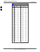
PN Offset Programming Information 68P09258A31–A Table B-1: PnMask I and PnMask Q Values for PilotPn Pilot PN 451 452 453 454 455 456 457 458 459 460 461 462 463 464 465 466 467 468 469 470 471 472 473 474 475 476 477 478 479 480 481 482 483 484 485 486 487 488 489 490 491 492 493 494 495 496 497 498 499 500 B I 14–Chip Delay Q (Dec.
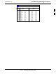
PN Offset Programming Information 68P09258A31–A Table B-1: PnMask I and PnMask Q Values for PilotPn Pilot PN 501 502 503 504 505 506 507 508 509 510 511 Oct 2003 I 14–Chip Delay Q (Dec.) 14301 23380 11338 2995 23390 14473 6530 20452 12226 1058 12026 19272 29989 8526 18139 3247 28919 7292 20740 27994 2224 6827 I (Hex.
PN Offset Programming Information 68P09258A31–A Notes B B-14 1X SCt 4812T BTS Optimization/ATP Oct 2003
C Appendix C FRU Optimization/ATP Test Matrix Oct 2003 1X SCt 4812T BTS Optimization/ATP C-1
FRU Optimization/ATP Test Matrix 68P09258A31–A FRU Optimization/ATP Test Matrix Usage & Background Periodic maintenance of a site may also may mandate re–optimization of specific portions of the site. An outline of some basic guidelines is included in the following tables. NOTE Re–optimization steps listed for any assembly detailed in the tables below must be performed anytime an RF cable associated with it is replaced.
FRU Optimization/ATP Test Matrix 68P09258A31–A Inter-frame Cabling Optimization must be performed after the replacement of any RF cabling between BTS frames. Table C-2: When to Optimize Inter–frame Cabling Item Replaced Optimize: Ancillary frame to BTS frame (RX) cables The affected sector/antenna RX paths. BTS frame to ancillary frame (TX) cables The affected sector/antenna TX paths.
FRU Optimization/ATP Test Matrix 68P09258A31–A D CSM LFR/HSO GPS GLI LPA Trunking Backplane LPA LPA Bandpass Filter Power Supply Modules Switch Card RFDS D MCC 2-15 Initial Power-up D BBX Table 2-7 D C–CCP Backplane 2-6 DC Power Pre-Test Physical 2-14 Inspect D MPC/EMPC Table 2-2 Table 2-5 D TX Cables 2-3 RX Filter Initial Boards/Modules Install, Prelimnary Operations, CDF Site Equipage; etc.
FRU Optimization/ATP Test Matrix 68P09258A31–A [ 4-9 Spectral Purity TX Mask ATP 4 4 Table 4-1 4-9 Waveform Quality (rho) ATP 4 4 Table 4-1 4-9 Pilot Time Offset ATP 4 4 Table 4-1 4-9 Code Domain Power / Noise Floor 4 4 Table 4-1 4-9 FER Test 5 5 1 2 3 4 5 6 7 8 1 1 4 * 3 3 4 4 1 1 6 * 3 3 4 RFDS LPA Bandpass Filter 4 Switch Card LPA * Power Supply Modules LPA Trunking Backplane 4 C 6 RFDS Path Calibration should be performed at initial BTS installation A
FRU Optimization/ATP Test Matrix 68P09258A31–A Notes C C-6 1X SCt 4812T BTS Optimization/ATP Oct 2003
Appendix D D BBX Gain Set Point vs.
BBX Gain Set Point vs. BTS Output Considerations 68P09258A31–A BBX Gain Set Point vs. BTS Output Considerations Usage & Background Table D-1 outlines the relationship between the total of all code domain channel element gain settings (digital root sum of the squares) and the BBX Gain Set Point between 33.0 dBm and 44.0 dBm. The resultant RF output (as measured at the top of the BTS in dBm) is shown in the table. The table assumes that the BBX Bay Level Offset (BLO) values have been calculated.
BBX Gain Set Point vs. BTS Output Considerations 68P09258A31–A Table D-1: BBX Gain Set Point vs. Actual BTS Output (in dBm) dBm’ Gainb 44 43 42 41 40 39 38 37 36 35 34 33 381 – – – – 43.3 42.3 41.3 40.3 39.3 38.3 37.3 36.3 374 – – – – 43.1 42.1 41.1 40.1 39.1 38.1 37.1 36.1 366 – – – 43.9 42.9 41.9 40.9 39.9 38.9 37.9 36.9 35.9 358 – – – 43.7 42.7 41.7 40.7 39.7 38.7 37.7 36.7 35.7 350 – – – 43.5 42.5 41.5 40.5 39.5 38.5 37.5 36.
BBX Gain Set Point vs.
Appendix E CDMA Operating Frequency E Oct 2003 1X SCt 4812T BTS Optimization/ATP E-1
Operating Frequency – North American PCS Bands 68P09258A31–A Operating Frequency – North American PCS Bands Introduction Programming of each of the BTS BBX synthesizers is performed by the BTS GLIs via the CHI bus. This programming data determines the transmit and receive transceiver operating frequencies (channels) for each BBX. 1900 MHz PCS Channels Figure E-1 shows the valid channels for the North American PCS 1900 MHz frequency spectrum.
68P09258A31–A Operating Frequency – North American PCS Bands Calculating 1900 MHz Center Frequencies Table E-1 shows selected 1900 MHz CDMA candidate operating channels, listed in both decimal and hexadecimal, and the corresponding transmit, and receive frequencies. Center frequencies (in MHz) for channels not shown in the table may be calculated as follows: S TX = 1930 + 0.05 * Channel# Example: Channel 262 TX = 1930 + 0.05*262 = 1943.10 MHz S RX = TX – 80 Example: Channel 262 RX = 1943.10 – 80 = 1863.
Operating Frequency – North American PCS Bands 68P09258A31–A Table E-1: 1900 MHz TX and RX Frequency vs. Channel Channel Number Decimal Hex E Transmit Frequency (MHz) Center Frequency Receive Frequency (MHz) Center Frequency 600 0258 1960.00 1880.00 625 0271 1961.25 1881.25 650 028A 1962.50 1882.50 675 02A3 1963.75 1883.75 700 02BC 1965.00 1885.00 725 02D5 1966.25 1886.25 750 02EE 1967.50 1887.50 775 0307 1968.75 1888.75 800 0320 1970.00 1890.00 825 0339 1971.
Operating Frequency – North American PCS Bands 68P09258A31–A 800 MHz CDMA Channels Figure E-2 shows the valid channels for the North American cellular telephone frequency spectrum. There are 10 CDMA wireline or non–wireline band channels used in a CDMA system (unique per customer operating system). OVERALL WIRELINE (B) BANDS ÉÉ ÉÉ ËË ËË 848.970 893.970 777 739 ËËË ËËË ËËË ËËË 799 891.480 891.510 846.480 846.510 716 717 694 ÉÉ ÉÉ ÉÉ ÉÉ 689 844.980 845.010 889.980 890.
Operating Frequency – North American PCS Bands 68P09258A31–A Table E-2: 800 MHz TX and RX Frequency vs. Channel Channel Number Decimal Hex E Transmit Frequency (MHz) Center Frequency Receive Frequency (MHz) Center Frequency 75 004B 872.2500 827.2500 100 0064 873.0000 828.0000 125 007D 873.7500 828.7500 150 0096 874.5000 829.5000 175 00AF 875.2500 830.2500 200 00C8 876.0000 831.0000 225 00E1 876.7500 831.7500 250 00FA 877.5000 832.5000 275 0113 878.2500 833.
Operating Frequency – Korean Bands 68P09258A31–A Operating Frequency – Korean Bands 1700 MHz PCS Channels Figure E-3 shows the valid channels for the 1700 MHz PCS frequency spectrum. The CDMA channels are spaced in increments of 25 (25, 50, 75, . . . 575) across the CDMA band. Figure E-3: 1700 MHz PCS Frequency Spectrum CHANNEL 25 FREQ (MHz) RX TX 1751.25 1841.25 E 575 Oct 2003 1778.75 1868.
Operating Frequency – Korean Bands 68P09258A31–A Calculating 1700 MHz Center Frequencies Center frequency for channels may be calculated as follows: Direction Formula Example TX 1840 + (0.05 * Channel#) Channel: 1840 + (0.05 + 25) = 1841.25 RX 1750 + (0.05 * Channel#) Channel: 1750 + (0.05 + 25) = 1751.25 – Actual frequencies used depend on customer CDMA system frequency plan. – Each CDMA channel requires a 1.77 MHz frequency segment. The actual CDMA carrier is 1.23 MHz wide, with a 0.
Appendix F Test Equipment Preparation F Oct 2003 1X SCt 4812T BTS Optimization/ATP F-1
Test Equipment Preparation 68P09258A31–A Test Equipment Preparation Purpose This appendix provides information on pre–testing set–up for the following test equipment items (not required for the Cybertest test set): S S S S S S S S S S S S Agilent E7495A test equipment setup Agilent E4406A transmitter test set Agilent E4432B signal generator Advantest R3267 spectrum analyzer Advantest R3562 signal generator Agilent 8935 analyzer (formerly HP 8935) HP 8921 with PCS interface analyzer Advantest R3465 analy
Test Equipment Preparation 68P09258A31–A Agilent R7495A Test Equipment Setup This test equipment requires a warm-up period of at least 30 minutes before BTS testing or calibration begins. Using the Agilent E7495A with the LMF The Agilent E7495A does not require the use of the 19MHz frequency reference; if connected, it will be ignored. The Even Sec SYNC connection is required. The Agilent E7495A signal generator is only calibrated down to –80db.
Test Equipment Preparation 68P09258A31–A Detecting Test Equipment Check that no other equipment is connected to the LMF. Agilent equipment must be connected to the LAN to detect it. Then perform the procedures described in Table F-2. Table F-2: Detecting Agilent E7495A Test Equipment n Step Action 1 Click the Tools Menu. 2 Choose Options. 3 Check Agilent E7495A option in non–GPIB Test Equipment and enter its IP number. 4 Click Apply and wait a moment. 5 Click Dismiss.
Test Equipment Preparation 68P09258A31–A Figure F-1: Agilent E7495A Pre–Power Sensor Calibration connection Power REF 50 MHz GPIO Serial 1 Port 2 RF In Sensor Ext Ref In Even Second Sync In Use only Agilent supplied power adapter Port 1 RF Out / SWR GPS Antenna Serial 2 POWER SENSOR NOT CONNECTED Figure F-2: Agilent E7495A Power Sensor Calibration connection POWER SENSOR CONNECTED GPIO Port 2 RF In Power REF 50 MHz Serial 1 Sensor Serial 2 Ext Ref In Even Second Sync In Use only Agilent
Verifying and Setting GPIB Address 68P09258A31–A Verifying and Setting GPIB Address Agilent E4406A Transmitter Tester GPIB Address Refer to Figure F-3 and follow the procedure in Table F-4 to verify and, if necessary, change the Agilent E4406A GPIB address.
Verifying and Setting GPIB Address 68P09258A31–A Agilent E4432B Signal Generator GPIB Address Refer to Figure F-4 and follow the procedure in Table F-5 to verify and, if necessary, change the Agilent E4432B GPIB address.
Verifying and Setting GPIB Address 68P09258A31–A Advantest R3267 Spectrum Analyzer GPIB Address Refer to Figure F-5 and perform the procedure in Table F-6 to verify and, if necessary, change the Advantest R3267 spectrum analyzer GPIB address.
Verifying and Setting GPIB Address 68P09258A31–A Advantest R3562 Signal Generator GPIB Address Set the GP–IB ADDRESS switch on the rear of the Advantest R3562 signal generator to address 1 as shown in Figure F-6.
Verifying and Setting GPIB Address 68P09258A31–A Agilent 8935 Series E6380 (formerly HP 8935) Test Set GPIB Address Refer to Figure F-7 and follow the procedure in Table F-7 to verify and, if necessary, change the Agilent 8935 GPIB address. Figure F-7: Agilent 8935 Test Set Preset Local Inst Config Shift NOTE Cursor Control FW00885 This procedure assumes that the test equipment is set up and ready for testing.
Verifying and Setting GPIB Address 68P09258A31–A Hewlett Packard HP8921A and HP83236A/B GPIB Address Refer to Figure F-8 and follow the procedure in Table F-8 to verify and, if necessary, change the HP 8921A HP 83236A GPIB addresses. Figure F-8: HP 8921A and HP 83236A/B Local Preset Cursor Control Shift NOTE This procedure assumes that the test equipment is set up and ready for testing.
Verifying and Setting GPIB Address 68P09258A31–A Advantest R3465 Communications Test Set GPIB Address Refer to Figure F-9 and follow the procedure in Table F-9 to verify and, if necessary, change the GPIB address for the Advantest R3465. Figure F-9: R3465 Communications Test Set GPIB and others REF UNLOCK BNC “T” EVEN SEC/SYNC IN CDMA TIME BASE IN POWER OFF ON Vernier Knob LCL Shift NOTE F Preset REF FW00337 This procedure assumes that the test equipment is set up and ready for testing.
Verifying and Setting GPIB Address 68P09258A31–A Motorola CyberTest GPIB Address Follow the steps in Table F-10 to verify and, if necessary, change the GPIB address on the Motorola CyberTest. Changing the GPIB address requires the following items: S S S S NOTE Motorola CyberTest communications analyzer. Computer running Windows 3.1/Windows 95. Motorola CyberTAME software program “TAME”. Parallel printer port cable (shipped with CyberTest).
Verifying and Setting GPIB Address 68P09258A31–A HP 437 Power Meter GPIB Address Refer to Figure F-10 and follow the steps in Table F-11 to verify and, if necessary, change the HP 437 GPIB address. Figure F-10: HP 437 Power Meter PRESET SHIFT (BLUE) PUSHBUTTON – ACCESSES FUNCTION AND DATA ENTRY KEYS IDENTIFIED WITH LIGHT BLUE TEXT ON THE FRONT PANEL ABOVE THE BUTTONS ENTER NOTE REF FW00308 This procedure assumes that the test equipment is set up and ready for testing.
Verifying and Setting GPIB Address 68P09258A31–A Gigatronics 8541C Power Meter GPIB Address Refer to Figure F-11 and follow the steps in Table F-12 to verify and, if necessary, change the Gigatronics 8541C power meter GPIB address. Figure F-11: Gigatronics 8541C Power Meter Detail 1 MENU NOTE ENTER ARROW KEYS REF FW00564 This procedure assumes that the test equipment is set up and ready for testing.
Verifying and Setting GPIB Address 68P09258A31–A RS232 GPIB Interface Adapter Be sure that the RS–232 GPIB interface adapter DIP switches are set as shown in Figure F-12.
Test Equipment Set-up 68P09258A31–A Test Equipment Set-up Purpose This section covers other test equipment and peripherals not covered in Chapter 3. Procedures for the manual testing are covered here, along with procedures to calibrate the TX and RX cables using the signal generator and spectrum analyzer. Equipment Warm up NOTE Warm-up BTS equipment for a minimum of 60 minutes prior to performing the BTS optimization procedure. This assures BTS site stability and contributes to optimization accuracy.
Test Equipment Set-up 68P09258A31–A HP8921A System Connectivity Test Follow the steps in Table F-13 to verify that the connections between the PCS Interface and the HP8921A are correct, and cables are intact. The software also performs basic functionality checks of each instrument. NOTE Disconnect other GPIB devices, especially system controllers, from the system before running the connectivity software.
Test Equipment Set-up 68P09258A31–A Manual Cable Calibration using HP8921 with HP PCS Interface (HP83236) NOTE This calibration method must be executed with great care. Some losses are measured close to the minimum limit of the power meter sensor (–30 dBm). Prerequisites Ensure the following prerequisites have been met before proceeding: S Test equipment to be calibrated has been connected correctly for cable calibration. S Test equipment has been selected and calibrated.
Test Equipment Set-up 68P09258A31–A Table F-14: Manual Cable Calibration Test Equipment Setup (using the HP PCS Interface) Step Action 9 Set the user fixed Attenuation Setting to 0 dBm: – Position cursor at Analyzer Attenuation and select it – Position cursor at User Fixed Atten Settings and select it. – Enter 0 (zero) using the numeric keypad and press [Enter]. 10 Select Back to Previous Menu.
Test Equipment Set-up 68P09258A31–A Table F-14: Manual Cable Calibration Test Equipment Setup (using the HP PCS Interface) Step Action 23 Click on Pause for Manual Measurement.
Test Equipment Set-up 68P09258A31–A Figure F-13: Calibrating Test Setup Components MEMORY CARD SLOT POWER SENSOR (A) (A) POWER SENSOR (B) (B) 20 dB / 20 WATT ATTENUATOR F POWER SENSOR (C) POWER SENSOR (C) 150 W NON–RADIATING RF LOAD F-22 30 dB DIRECTIONAL COUPLER 1X SCt 4812T BTS Optimization/ATP FW00292 Oct 2003
Test Equipment Set-up 68P09258A31–A HP PCS Interface Test Equipment Setup for Manual Testing Follow the procedure in Table F-15 to setup the HP PCS Interface Box for manual testing. Table F-15: HP PCS Interface Test Equipment Setup for Manual Testing n Step Action NOTE Verify GPIB controller is turned off. 1 Insert HP83236B Manual Control/System card into the memory card slot. 2 Under Screen Controls, press the [TESTS] push-button to display the TESTS (Main Menu) screen.
Test Equipment Set-up 68P09258A31–A Calibrating Test Cable Setup using Advantest R3465 NOTE Be sure the GPIB Interface is OFF for this procedure. Perform the procedure in Table F-16 to calibrate the test cable setup using the Advantest R3465. Advantest R3465 Manual Test setup and calibration must be performed at both the TX and RX frequencies.
Test Equipment Set-up 68P09258A31–A Table F-16: Procedure for Calibrating Test Cable Setup Using Advantest R3465 Step Action NOTE The Power Meter sensor lower limit is –30 dBm. Thus, only components having losses < 30 dB should be measured using this method. For best accuracy, always re–zero the power meter before connecting the power sensor to the component being calibrated. Then, after connecting the power sensor to the component, record the calibrated loss immediately.
Test Equipment Set-up 68P09258A31–A Figure F-14: Cable Calibration using Advantest R3465 RF OUT POWER SENSOR (A) & (B) (C) F POWER SENSOR 20 DB / 2 WATT ATTENUATOR POWER SENSOR (C) POWER SENSOR (D) 100 W NON–RADIATING RF LOAD F-26 FW00320 30 DB DIRECTIONAL COUPLER 1X SCt 4812T BTS Optimization/ATP Oct 2003
Test Equipment Set-up 68P09258A31–A Agilent E4406A Transmitter Tester Self-alignment (Calibration) The Agilent E4406A requires pre–calibration actions or calibration verification that are not supported by the LMF. Follow the procedure in Table F-17 and refer to Figure F-15 to perform the Agilent E4406A self–alignment (calibration). Table F-17: Agilent E4406A Self–alignment (Calibration) Step Action 1 In the SYSTEM section of the instrument front panel, press the System key.
Test Equipment Set-up 68P09258A31–A Notes F F-28 1X SCt 4812T BTS Optimization/ATP Oct 2003
Appendix G Download ROM Code G Oct 2003 1X SCt 4812T BTS Optimization/ATP G-1
Download ROM Code 68P09258A31–A Download ROM Code Download ROM Code ROM code can be downloaded to a device that is in any state. After the download is started, the device being downloaded changes to OOS_ROM (blue) and remains OOS_ROM (blue). The same R–level RAM code must then be downloaded to the device. This procedure includes steps for both the ROM code download and the RAM code download. ROM code files cannot be selected automatically. The ROM code file must be selected manually.
Download ROM Code 68P09258A31–A Table G-1: Download ROM Code Step Action 6 From the BTS menu bar Device pull–down menus, select Download > ROM. – If the file matching the Hardware Binary Type of the device is found in the code folder, a status report shows the result of the download. Proceed to Step 12. – If a file selection window appears, select the ROM code file manually. 7 Double–click on the version folder that contains the desired ROM code file. 8 Double–click on the Code folder.
Download ROM Code 68P09258A31–A Table G-1: Download ROM Code Step Action 23 Click on the device that was downloaded. 24 Click on the Device menu. 25 Click on the Status menu item. Verify that the status report window displays the correct ROM and RAM version numbers. Click on the Ok button to close the status report window.
Appendix H In–Service Calibration H Oct 2003 1X SCt 4812T BTS Optimization/ATP H-1
Introduction 68P09258A31–A Introduction Purpose This procedure is a guide to expanding your system with multiple carriers while the system remains in service. This procedure also allows you to perform on site maintenance (replace defective boards and recalibrate) while the remainder of the site stays in service. Motorola recommends that you perform this procedure during a maintenance window. This procedure cannot be performed on BTSs with 4–to–1 combiners.
Power Delta Calibration 68P09258A31–A Power Delta Calibration Power Delta Calibration Introduction The In–service calibration procedure has several differences from a normal calibration procedure. One of these is the use of a spectrum analyzer instead of a power meter to measure power. Power meters are broadband measurement devices and cannot be used to measure power during In–service Calibration since other carriers are operating.
Power Delta Calibration 68P09258A31–A Table H-1: HP8921A Power Delta Calibration Procedure Step Action 7 Ensure that the source HP8921A settings are the same as in Step 2. 8 Set the measuring HP8921A as follows: – Measure mode to CDMA Anl – Frequency to the CDMA calibration target frequency – Input Attenuation to 0 dB – Input port to RF–IN – Gain to Auto – Analyzer Direction to Fwd 9 Turn on the source HP8921A signal output.
Power Delta Calibration 68P09258A31–A Figure H-2: Delta Calibration Setup – HP8921A to HP8921A Measurement HP8921A Source HP8921A DUPLEX OUT RF IN/OUT Short RF Cable FW00802 Advantest R3465 Power Delta Calibration Follow the procedure in Table H-2 to perform the Advantest R3465 Power Delta Calibration procedure. Table H-2: Advantest Power Delta Calibration Procedure Step Action NOTE Perform this procedure after test equipment has been allowed to warm–up and stabilize for a minimum of 60 minutes.
Power Delta Calibration 68P09258A31–A Table H-2: Advantest Power Delta Calibration Procedure Step H Action 13 Record the Power Meter reading as result A ________________________. 14 Press the Output CRT menu key to toggle the Output to OFF. 15 Connect the RF cable from the R3561L CDMA Test Source Unit RF OUT port to the Spectrum Analyzer INPUT Port (see Figure H-4). 16 Press the Output CRT menu key to change the Output to ON. 17 Press the CW key in the Measurement area of the control panel.
Power Delta Calibration 68P09258A31–A Table H-2: Advantest Power Delta Calibration Procedure Step Action 40 Calculate the Power Calibration Delta value. The delta value is the power meter measurement minus the Advantest measurement. Delta = A – B Example: Delta = –0.70 dBm – (–1.25 dBm) = 0.55 dBm Example: Delta = 0.26 dBm – 0.55 dBm = –0.29 dBm These examples are included to show the mathematics and do not represent actual readings.
Power Delta Calibration 68P09258A31–A HP8935 Power Delta Calibration Follow the procedure in Table H-3 to perform the HP8935 Power Delta Calibration procedure. Table H-3: HP8935 Power Delta Calibration Procedure Step Action NOTE Perform this procedure after test equipment has been allowed to warm–up and stabilize for a minimum of 60 minutes. 1 Connect a short RF cable between the HP8935 Duplex Out port and the HP437B power sensor (see Figure H-5).
Power Delta Calibration 68P09258A31–A Table H-3: HP8935 Power Delta Calibration Procedure Step Action 13 Calculate the Power Calibration Delta value. The delta value is the power meter measurement minus the Advantest measurement. Delta = A – B Example: Delta = –0.70 dBm – (–1.25 dBm) = 0.55 dBm Example: Delta = 0.26 dBm – 0.55 dBm = –0.29 dBm These examples are included to show the mathematics and do not represent actual readings.
Power Delta Calibration 68P09258A31–A Agilent E4406A Power Delta Calibration The Agilent E4406A transmitter tester and E4432B signal generator test equipment combination can be used for ISC of IS–2000 CDMA 1X as well as IS–95A/B operation modes. The power delta calibration is performed on the E4406A, but the E4432B is required to generate the reference signal used to calculate the power delta offset. After the offset value has been calculated, add it to the TX cable loss value in the LMF.
Power Delta Calibration 68P09258A31–A Table H-4: Agilent E4406A Power Delta Calibration Procedure Step Action NOTE Do not change the frequency and amplitude settings on the E4432B when performing the following steps. 8 Set the E4406A as follows: – Press Preset to exit any modes for which the transmitter tester is configured. – Press MODE and, using the soft keys to the right of the screen, select cdmaOne. – Press MEASURE and, using the soft keys, select spectrum.
Power Delta Calibration 68P09258A31–A Figure H-7: Delta Calibration Setup – Agilent E4432B to HP437 AGILENT E4432B AND E4406A HP437B SENSOR RF OUTPUT Power Sensor Short RF Cable FW00858 Figure H-8: Delta Calibration Setup – Agilent E4432B to Agilent E4406A AGILENT E4432B AND E4406A RF OUTPUT Short RF Cable RF INPUT FW00859 H H-12 1X SCt 4812T BTS Optimization/ATP Oct 2003
In–Service Calibration 68P09258A31–A In–Service Calibration CAUTION This feature does NOT have fault tolerance at this time. The system has no safe–guards to stop you from doing something that will take the BTS out of service. If possible, perform this procedure during a maintenance window. Follow the procedures in this section precisely, otherwise the entire BTS will most likely go OUT OF SERVICE. At the CBSC, only perform operations on expansion hardware when it is in the OOS_MANUAL state.
In–Service Calibration 68P09258A31–A Figure H-9: Optimization/ATP Test Setup Using RFDS TEST SETS Optimization/ATP SET UP Hewlett–Packard Model HP 8935 SYNC MONITOR EVEN SEC TICK PULSE REFERENCE FROM CSM BOARD FREQ MONITOR 19.6608 MHZ CLOCK REFERENCE FROM CSM BOARD HP–IB TO GPIB BOX NOTE: IF BTS RX/TX SIGNALS ARE DUPLEXED: BOTH THE TX AND RX TEST CABLES CONNECT TO THE DUPLEXED ANTENNA GROUP. 20 DB PAD (FOR 1.7/1.
In–Service Calibration 68P09258A31–A Figure H-10: IS–95 A/B/C Optimization/ATP Test Setup Using RFDS TEST SETS Optimization/ATP SET UP Advantest R3267 (Top) and R3562 (Bottom) NOTE: IF BTS RX/TX SIGNALS ARE DUPLEXED: BOTH THE TX AND RX TEST CABLES CONNECT TO THE DUPLEXED ANTENNA GROUP. RX TEST CABLE TO EXT TRIG ON REAR OF SPECTRUM ANALYZER ANTENNA RF IN TX TEST CABLE BNC “T” EXT TRIG IN RF OUT NOTE: FREQ MONITOR 19.
In–Service Calibration 68P09258A31–A Follow the procedure in Table H-5 to perform the In–Service Calibration. Table H-5: In–Service Calibration Step Action NOTE Perform this procedure after test equipment has been allowed to warm–up and stabilize for a minimum of 60 minutes. 1 Set up the LMF for In–Service Calibration: – Start the LMF by double–clicking the LMF icon on the Windows desktop. – Click Tools>Options from the menu bar at the login screen.
In–Service Calibration 68P09258A31–A Table H-5: In–Service Calibration Step Action 5 Input the Coupler Loss for the TX and RX tests: – Click Util>Edit>Coupler Loss>TX or RX from the menu bar at the main window. – Input the appropriate coupler loss for the target carrier(s) by referring to the information taken at the time of BTS installation. – Click the Save button. – Click the Dismiss button to close the window. – To view the coupler loss file, click Util>Examine>Coupler Loss>TX or RX.
In–Service Calibration 68P09258A31–A Table H-5: In–Service Calibration Step Action ! CAUTION Perform the In–service Calibration procedure on OOS devices only. 8 Select the desired test: – Select the target BBX(s) on the C–CCP cage picture. – Click Tests>[desired test] from the menu bar at the main window. – Select the target carrier and confirm the channel number in the pop up window. – Leave the Verify BLO check box checked. – From the Test Pattern pick list, select a test pattern.
Appendix I VSWR I Oct 2003 1X SCt 4812T BTS Optimization/ATP I-1
Transmit & Receive Antenna VSWR 68P09258A31–A Transmit & Receive Antenna VSWR Purpose The following procedures will verify that the Voltage Standing Wave Ratio (VSWR) of all antennas and associated feed lines fall within acceptable limits. The tests will be performed on all antennas in a sequential manner (i.e., ANT 1, then ANT 2) until all antennas/feedlines have been verified.
Transmit & Receive Antenna VSWR 68P09258A31–A Equipment Setup – HP Test Set Follow the procedure in Table I-1 to set up test equipment required to measure and calculate the VSWR for each antenna. Table I-1: VSWR Measurement Procedure – HP Test Set Step Action HP TEST SET 1 If you have not already done so, refer to the procedure in Table 3-5 on page 3-17 to set up test equipment & interface the LMF computer to the BTS.
Transmit & Receive Antenna VSWR 68P09258A31–A Table I-1: VSWR Measurement Procedure – HP Test Set Step 5 HP TEST SET Action Calculate the VSWR per the equation shown to the right. Where: RL(dB) = PA(dBm) – PS(dBm) PA = Power reflected from antenna PS = Power reflected from short A calculated value of –13.98 dB equates to VSWR of better than 1.5:1.
Transmit & Receive Antenna VSWR 68P09258A31–A Figure I-2: Manual VSWR Test Setup Using HP8921 Test Set (800 MHz) FEED LINE TO ANTENNA UNDER TEST RVS (REFLECTED) PORT INPUT PORT RF SHORT 30 DB DIRECTIONAL COUPLER OUTPUT PORT FWD (INCIDENT) PORT 50–OHM TERMINATED LOAD FW00343 Equipment Setup – Advantest Test Set Follow the steps in Table I-2 to set up test equipment required to measure and calculate the VSWR for each antenna.
Transmit & Receive Antenna VSWR 68P09258A31–A Table I-2: VSWR Measurement Procedure – Advantest Test Set Step 3 Action ADVANTEST Preform the following to instruct the calibrated test set to generate a CDMA RF carrier (RVL call) with all zero longcode at the assigned RX frequency at –10 dBm: S Push the ADVANCE Measurement key. S Push the CDMA Sig CRT menu key.
Transmit & Receive Antenna VSWR 68P09258A31–A Table I-2: VSWR Measurement Procedure – Advantest Test Set Step ADVANTEST Action 9 If the readings indicate a potential problem, verify the physical integrity of all cables (including any in–line components, pads, etc.) and associated connections up to the antenna. If problem still persists, consult antenna OEM documentation for additional performance verification tests or replacement information.
Transmit & Receive Antenna VSWR 68P09258A31–A Notes I I-8 1X SCt 4812T BTS Optimization/ATP Oct 2003
Appendix J Packet Backhaul Configuration J Oct 2003 1X SCt 4812T BTS Optimization/ATP J-1
BTS Router Initial Configuration 68P09258A31–A BTS Router Initial Configuration Overview This appendix contains information and operations related to loading an MWR 1941 BTS router with the minimum standard (canned) configuration necessary for network communications. Once the router is communicating on the network, the full, site-specific, operational configuration can be downloaded to the router over the network.
Terminal Setup 68P09258A31–A Terminal Setup General This section provides the procedures to configure and save a terminal session for communicating with the MWR 1941 BTS router. Terminal settings are the same as those used for BTS card and module Man–Machine Interface (MMI) communication sessions. The procedures are for a Pentiumr processor–based computer operating with either Windows 98 Second Edition (SE) or Windows 2000.
Terminal Setup 68P09258A31–A Table J-1: Establish HyperTerminal Connection Step Action 4 From the Connect using: pick list in the Connect To box displayed, select the RS–232 port to be used for the connection (e.g., COM1 or COM2 – Win2000 or Direct to Com 1 or Direct to Com 2 – Win98), and click OK.
Terminal Setup 68P09258A31–A Table J-1: Establish HyperTerminal Connection Step Action 19 If desired, reposition the shortcut icon for the new connection by dragging it to another location on the Windows desktop. NOTE The shortcut icon can now be double–clicked to open a BTS router or BTS card/module MMI HyperTerminal session without the need to negotiate multiple menu levels.
Terminal Setup 68P09258A31–A Figure J-2: Wiring Diagram, DB–9 Plug–to–8–contact Modular Plug Adapter Adapter DB–9 Receptacle Socket Numbering (Mating Side) 5 4 3 2 1 DB–9 Receptacle 8–contact Modular Receptacle 1 NC 2 6 3 3 Adapter 8–contact Receptacle Contact Numbering (Mating Side) 4 2 12 34567 8 5 5 4 9 8 7 6 6 7 7 1 8 8 9 NC Table J-2: Establishing BTS Router Serial Communication Step Action 1 If it has not been done, start the computer and allow it to complete boot–up.
Terminal Setup 68P09258A31–A Figure J-3: LMF Computer Connections to BTS Router ROLLOVER CABLE To BTS router CONSOLE receptacle DB9–TO–RJ48C ADAPTER LMF COMPUTER OR EQUIVALENT COM1 OR COM2 OPTOATP0001–0 J Oct 2003 1X SCt 4812T BTS Optimization/ATP J-7
Downloading Minimum Canned BTS Router Configuration Files 68P09258A31–A Downloading Minimum Canned BTS Router Configuration Files Downloading Overview After they are generated on the OMC–R, the BTS router canned configuration files must be transferred to another computer platform from which they can be installed into the BTS routers. A number of procedures may be used to move the canned configuration files from the OMC–R to a platform from which they can be loaded into the routers.
Downloading Minimum Canned BTS Router Configuration Files 68P09258A31–A Table J-3: BTS Router Canned Configuration File FTP Transfer from the OMC–R Step 3 Action Connect the LMF computer to the local network and log on. NOTE This procedure uses the command line FTP client supplied with Windows 98, Second Edition (Win98 SE) and Windows 2000 (Win2K); however, any commercially available FTP client application can be used. Follow the manufacturer’s instructions for operation of an alternative application.
Downloading Minimum Canned BTS Router Configuration Files 68P09258A31–A Table J-3: BTS Router Canned Configuration File FTP Transfer from the OMC–R Step 9 Action Enter the User ID and password when prompted, pressing the Enter key after each. A response similar to the following will be displayed: User (OMCR–1:(none)): scadm 331 Password required for scadm. Password: 230 User scadm logged in.
68P09258A31–A Downloading Minimum Canned BTS Router Configuration Files Table J-3: BTS Router Canned Configuration File FTP Transfer from the OMC–R Step Action 13 Change to the binary transfer mode and, if desired, turn on hash mark printing for transfer progress by entering the following, pressing the Enter key after each command: bin hash A response similar to the following will be displayed: ftp> bin 200 Type set to I. ftp> hash Hash mark printing On ftp> ftp: (2048 bytes/hash mark) .
Downloading Minimum Canned BTS Router Configuration Files 68P09258A31–A Table J-3: BTS Router Canned Configuration File FTP Transfer from the OMC–R Step 15 Action Before terminating the FTP session, open Windows Explorer and view the contents of the directory where the canned configuration files are to be stored to be sure the files are present. Perform the following: 15a – Click Start > Programs > Windows Explorer.
68P09258A31–A Verifying IOS Canned Version of the CF Memory Card Verifying IOS Canned Version of the CF Memory Card Overview This section covers the procedures and commands required to verify the IOS version loaded on BTS router CF memory cards and copy standard canned configuration files to the routers.
Verifying IOS Canned Version of the CF Memory Card 68P09258A31–A Installation Methods – The startup–config configuration file used by the BTS router during initialization is stored in NVRAM. This is a memory device internal to the router and is separate from the CF memory card. To install the canned configuration file so the router will use it during boot–up, the file must be copied into the startup–config file in NVRAM. There are two methods available to accomplish this: 1.
Verifying IOS Canned Version of the CF Memory Card 68P09258A31–A Method 1: Using a TFTP Server to Load to CF Memory Card Required Equipment and Software The following items are required to perform this procedure: S A Windows–based computer which meets the requirements of the LMF computer platform as specified in this manual.
Verifying IOS Canned Version of the CF Memory Card 68P09258A31–A Required Publications The following publications are required to perform procedures in this section: S this manual S Cellular System Administration – CDMA OnLine Documentation S MWR1941 Wireless Mobile Edge Router Software Configuration Guide; part number 78–13983–01 Preparation for Canned Configuration File TFTP Transfer to CF Memory Card Preparation for a canned configuration file tftp transfer consists of the following activities: 1.
Verifying IOS Canned Version of the CF Memory Card 68P09258A31–A Table J-4: Set LMF Computer NIC IP Address and Create a Default TFTP Directory Step Action 1 Start the computer. 2 Login and allow the computer to boot to the desktop. 3 Depending on the installed operating system, from the Windows Start menu, select one of the following: S Win2000: Settings > Network and Dial–up Connections S Win98: Settings > Control Panel and double–click Network.
Verifying IOS Canned Version of the CF Memory Card 68P09258A31–A Table J-4: Set LMF Computer NIC IP Address and Create a Default TFTP Directory Step Action 9 In the Internet Protocol (TCP/IP) Properties dialog box which appears (Win2000) or the IP Address tab of the TCP/IP Properties dialog box (Win98), perform the following: 9a – If a black dot is not showing in the the radio button circle next to Use the following IP address: (Win2000) or Specify an IP address (Win98), click on the radio button.
Verifying IOS Canned Version of the CF Memory Card 68P09258A31–A Install and configure tftp server application To obtain, install, and configure the Cisco or PumpKIN tftp software applications, refer to the Setting Up the TFTP Server – Procedure in Cellular System Administration – CDMA OnLine Documentation For other tftp server applications, install and configure the application according to the manufacturer’s instructions.
Verifying IOS Canned Version of the CF Memory Card 68P09258A31–A Table J-5: Connecting the LMF Computer to the BTS Router for TFTP File Transfer Step Action 1 If the BTS router has not been connected to a power source, be sure the +27 Vdc power source is not on, and connect it to the router. 2 Connect the LMF computer to the BTS router as shown in Figure J-4, referring to the list of required equipment in this section as required.
Verifying IOS Canned Version of the CF Memory Card 68P09258A31–A Table J-6: BTS Router Power–up and Initial Ethernet Configuration Step 4 Action If a message similar to the following, is displayed type no and press the Enter key: Basic management setup configures only enough connectivity for management of the system, extended setup will ask you to configure each interface on the system Would you like to enter basic management setup? [yes/no]: A response similar to the following will be displayed: Would
Verifying IOS Canned Version of the CF Memory Card 68P09258A31–A Table J-6: BTS Router Power–up and Initial Ethernet Configuration Step 7 Action At the global configuration mode prompt, type each of the following commands, pressing the Enter key after each command: hostname btsrtr1 interface fa0/0 ip address 100.100.100.2 255.255.255.
Verifying IOS Canned Version of the CF Memory Card 68P09258A31–A Verifying IOS Version and Canned Configuration File TFTP Transfer to the BTS Router Prerequisites – The following is required prior to performing this procedure: S A copy of the required MWR 1941 router IOS version file is installed in the default tftp directory (transfer the file to the LMF computer using FTP, internet download, or media such as a Zip disk; file size is approximately 7–8 MB) IOS verification and canned configuration file
Verifying IOS Canned Version of the CF Memory Card 68P09258A31–A Table J-7: Transfer Canned Configuration Files to the BTS Router Using a TFTP Server Step 5 Action Begin verification that the CF memory card contains the correct version of the Cisco IOS by entering the following: dir slot0: A response similar to the following will be displayed: BTSRTR1#dir slot0: Directory of slot0:/ 1 –rw– 7051976 Mar 01 1993 00:11:34 mwr1941–i–mz.122–8.MC2a.
68P09258A31–A Verifying IOS Canned Version of the CF Memory Card Table J-7: Transfer Canned Configuration Files to the BTS Router Using a TFTP Server Step 6 Action Direct the router to show the version information by entering the following: show version A response similar to the following will be displayed: BTSRTR1#sh ver Cisco Internetwork Operating System Software IOS (tm) 1941 Software (MWR1941–I–M), Version 12.2(8)MC2a, EARLY DEPLOYMENT RELEASE SOFTWARE (fc1) TAC Support: http://www.cisco.
Verifying IOS Canned Version of the CF Memory Card 68P09258A31–A Table J-7: Transfer Canned Configuration Files to the BTS Router Using a TFTP Server Step Action CAUTION The file sequence on the CF memory card can not be verified with application programs which place the listed file names in alphabetical order (for example, certain Unix telnet applications, Unix directory listing commands, and Windows file managers such as Windows Explorer).
Verifying IOS Canned Version of the CF Memory Card 68P09258A31–A Table J-7: Transfer Canned Configuration Files to the BTS Router Using a TFTP Server Step 11 Action At the prompt for the remote host address or name, enter the IP address of the LMF computer NIC: 100.100.100.1 A response similar to the following will be displayed: BTSRTR1#copy tftp:btsrtr_canned.blue slot0:canned–config Address or name of remote host []? 100.100.100.
Verifying IOS Canned Version of the CF Memory Card 68P09258A31–A Table J-7: Transfer Canned Configuration Files to the BTS Router Using a TFTP Server Step Action 17 Scroll the HyperTerminal window back to the slot0: directory display obtained in step 13, above. 18 Compare the file size of startup–config to the canned configuration file to verify the copy operation. File sizes should be the same.
Verifying IOS Canned Version of the CF Memory Card 68P09258A31–A Method 2: Using a CF Memory Card Reader to Load CF Memory Card Required Equipment and Software The following items are required to perform this procedure: S A Windows–based computer which meets the requirements of the LMF computer platform as specified in this manual.
Verifying IOS Canned Version of the CF Memory Card 68P09258A31–A using a HyperTerminal connection. Attempting to format a CF memory card from a Windows–based computer using a card reader could result in unpredictable BTS router operation. CAUTION Do not format BTS router CF memory cards using a Windows–based computer. Only format CF memory cards in a BTS router.
68P09258A31–A Verifying IOS Canned Version of the CF Memory Card Table J-8: Transfer Canned Configuration File to CF Memory Card with CF Memory Card Reader Step Action 2 Connect the LMF computer to the BTS router and start a HyperTerminal communication session with the router by following the procedure in Table J-2. 3 If it has not been done, be sure the +27 Vdc power supply output is OFF, and connect the BTS router to the +27 Vdc power supply.
Verifying IOS Canned Version of the CF Memory Card 68P09258A31–A Table J-8: Transfer Canned Configuration File to CF Memory Card with CF Memory Card Reader Step 12 Action NOTE The CF memory card reader will appear as a disk drive in Windows Explorer with a disk drive letter and icon. Scroll the left–hand pane of Windows Explorer to locate the icon for the CF memory card.
Verifying IOS Canned Version of the CF Memory Card 68P09258A31–A Table J-8: Transfer Canned Configuration File to CF Memory Card with CF Memory Card Reader Step Action 22 Remove the CF memory card with the IOS version and canned configuration file from the card reader, and mark the card label with the canned configuration (blue or red) copied to it. 23 Install the CF memory card in the BTS router by following the procedure in the 1X SC 4812T BTS FRU Guide .
Verifying IOS Canned Version of the CF Memory Card 68P09258A31–A Table J-9: Copy Canned Configuration File to BTS Router Startup Configuration and Verify IOS File Position Step 4 Action NOTE The IOS defaults to the CF memory card (slot0:) directory unless the present working directory has been changed using the cd command. Determine the present working directory by entering pwd . If the present working directory has been changed, enter the command cd slot0: to return to the default setting.
Verifying IOS Canned Version of the CF Memory Card 68P09258A31–A Table J-9: Copy Canned Configuration File to BTS Router Startup Configuration and Verify IOS File Position Step 9 Action If desired, the contents of the startup–config file may be verified against the file listings at the end of this appendix for the blue or red canned configuration, as applicable, by entering the following: show startup–config NOTE Pressing the space bar at the MORE prompt will scroll another screen–full of data.
Replacing Installed BTS Router CF Memory Card IOS Version 68P09258A31–A Replacing Installed BTS Router CF Memory Card IOS Version Background BTS routers are supplied with CF memory cards pre–loaded with a version of the IOS. Prior to installing the routers in a BTS, the loaded IOS version should be verified as being the one required for the network. It is critical to also verify that the IOS file is the first file on the CF memory card.
68P09258A31–A Replacing Installed BTS Router CF Memory Card IOS Version Method 1: Replacement of Installed Router CF Card IOS Data Description This procedure covers using an LMF computer equipped with a tftp server application to perform the following activities: 1. Verify the IOS version loaded on a CF memory card and running on a BTS router 2. Replace the IOS version installed in a BTS router 3.
Replacing Installed BTS Router CF Memory Card IOS Version 68P09258A31–A Table J-10: Using a TFTP Server Application for Replacing Loaded IOS Version and Verifying File Sequence Position Step Action * IMPORTANT This procedure does not cover all aspects of BTS router operation and programming. Before performing this procedure, review BTS router initialization, operation, and programming information and procedures in MWR1941 Wireless Mobile Edge Router Software Configuration Guide; part number 78–13983–01.
68P09258A31–A Replacing Installed BTS Router CF Memory Card IOS Version Table J-10: Using a TFTP Server Application for Replacing Loaded IOS Version and Verifying File Sequence Position Step 5 Action If the default filename displayed in the prompt is correct, press the Enter key to accept it. If it is missing or not correct, enter the correct filename. A response similar to the following will be displayed if the default filename is selected: Address or name of remote host []? 100.100.100.
Replacing Installed BTS Router CF Memory Card IOS Version 68P09258A31–A Table J-10: Using a TFTP Server Application for Replacing Loaded IOS Version and Verifying File Sequence Position Step 9 Action If the default filename displayed in the prompt is correct, press the Enter key to accept it. If it is missing or not correct, enter the correct filename. A response similar to the following will be displayed: Destination filename [canned–config]? ! [OK – 2212/4096 bytes] 2212 bytes copied in 0.
68P09258A31–A Replacing Installed BTS Router CF Memory Card IOS Version Table J-10: Using a TFTP Server Application for Replacing Loaded IOS Version and Verifying File Sequence Position Step Action 15 Begin to copy the required version of the IOS from the LMF computer to the BTS router by entering the following: copy tftp:new_IOS_filename slot0: Where new_IOS_filename = the filename of the required IOS for the BTS router.
Replacing Installed BTS Router CF Memory Card IOS Version 68P09258A31–A Table J-10: Using a TFTP Server Application for Replacing Loaded IOS Version and Verifying File Sequence Position Step 19 Action Display the CF memory card directory to verify that the new IOS file is there by entering the dir command. A response similar to the following will be displayed: BTSRTR1#dir Directory of slot0:/ 1 –rw– 7051976 Sep 23 2002 07:25:36 mwr1941–i–mz.122–8.MC2a.
Replacing Installed BTS Router CF Memory Card IOS Version 68P09258A31–A Table J-10: Using a TFTP Server Application for Replacing Loaded IOS Version and Verifying File Sequence Position Step Action CAUTION The file sequence on the CF memory card can not be verified with application programs which place the listed file names in alphabetical order (for example, certain Unix telnet applications, Unix directory listing commands, and Windows file managers such as Windows Explorer).
Replacing Installed BTS Router CF Memory Card IOS Version 68P09258A31–A Table J-10: Using a TFTP Server Application for Replacing Loaded IOS Version and Verifying File Sequence Position Step 36 Action If no other BTS router file operations or configuration actions are required, perform the following: 36a – Remove power from the router and disconnect it from the power supply. 36b – Disconnect all other cabling from the BTS router.
68P09258A31–A Replacing Installed BTS Router CF Memory Card IOS Version File operations using a CF memory card reader – Only file transfers should be performed using the CF memory card reader. CF memory card formatting should be performed in a BTS router using a HyperTerminal connection. Attempting to format a CF memory card from a Windows–based computer using a card reader could result in unpredictable BTS router operation. CAUTION Do not format BTS router CF memory cards using a Windows–based computer.
Replacing Installed BTS Router CF Memory Card IOS Version 68P09258A31–A Table J-11: Using a CF Memory Card Reader for Replacing Loaded IOS Version and Verifying File Sequence Position Step Action 4 When all files on the CF memory card have been deleted or moved, as applicable, highlight the directory in the left–hand pane where the required IOS version and canned configuration files are stored.
Replacing Installed BTS Router CF Memory Card IOS Version 68P09258A31–A Table J-11: Using a CF Memory Card Reader for Replacing Loaded IOS Version and Verifying File Sequence Position Step Action NOTE The IOS present working directory defaults to the CF memory card (slot0:) directory unless the present working directory has been changed using the cd command. Determine the present working directory by entering pwd .
Replacing Installed BTS Router CF Memory Card IOS Version 68P09258A31–A Change CF Memory Card File Sequence to Place IOS File First on the Card This procedure covers using an LMF computer equipped with a CF memory card reader to perform the following activities: 1. Change the sequence of files on a CF memory card to place the IOS version file first 2.
Replacing Installed BTS Router CF Memory Card IOS Version 68P09258A31–A Table J-12: Use CF Memory Card Reader to Place IOS File First in CF Memory Card File Sequence Step Action CAUTION The file sequence on the CF memory card can not be verified with application programs which place the listed file names in alphabetical order (for example, certain Unix telnet applications, Unix directory listing commands, and Windows file managers such as Windows Explorer).
Replacing Installed BTS Router CF Memory Card IOS Version 68P09258A31–A Table J-12: Use CF Memory Card Reader to Place IOS File First in CF Memory Card File Sequence Step 7 7a Action Configure FE port FE 0 (fa0/0) by performing the following: – At the Router> user EXEC mode prompt, enter the following to access the privileged EXEC mode: enable A response similar to the following will be displayed: Router>enable Router# 7b – At the Router# privileged EXEC mode prompt, enter the following to access the
Replacing Installed BTS Router CF Memory Card IOS Version 68P09258A31–A Table J-12: Use CF Memory Card Reader to Place IOS File First in CF Memory Card File Sequence Step 7e Action – Verify port FE 0 (fa0/0) is configured with the correct IP address by entering the following: show ip interface brief A response similar to the following will be displayed: BTSRTR1#sh ip int br Interface IP Address OK? FastEthernet0/0 100.100.100.
Replacing Installed BTS Router CF Memory Card IOS Version 68P09258A31–A Table J-12: Use CF Memory Card Reader to Place IOS File First in CF Memory Card File Sequence Step Action 14 Use the tftp server to copy the IOS file from the LMF computer to the CF memory card by enteringthe following: copy tftp:IOS_filename slot0: Where IOS_filenamer = required IOS version filename in the LMF computer tftp server root directory.
Replacing Installed BTS Router CF Memory Card IOS Version 68P09258A31–A Table J-12: Use CF Memory Card Reader to Place IOS File First in CF Memory Card File Sequence Step 17 Action Display the directory of the CF memory card to confirm the IOS file transfer by entering the dir command. A response similar to the following will be displayed: Router#dir Directory of slot0:/ 1 –rw– 7051976 Sep 23 2002 07:24:18 mwr1941–i–mz.122–8.MC2a.
Replacing Installed BTS Router CF Memory Card IOS Version 68P09258A31–A Table J-12: Use CF Memory Card Reader to Place IOS File First in CF Memory Card File Sequence Step 23 Action If the IOS is not the first file displayed, as shown in step 2, above, format the CF memory card by entering the following: format slot0: A response similar to the following will be displayed: BTSRTR1#format slot0: Format operation may take a while.
68P09258A31–A Replacing Installed BTS Router CF Memory Card IOS Version Table J-12: Use CF Memory Card Reader to Place IOS File First in CF Memory Card File Sequence Step Action 31 If this procedure was entered from step 20 of Table J-11, return to Table J-11, step 21. 32 If no other BTS router file operations or configuration actions are required, perform the following: 32a – Remove power from the router and disconnect it from the power supply. 32b – Disconnect all cabling from the BTS router.
Verify and Upgrade rommon Version 68P09258A31–A Verify and Upgrade rommon Version Introduction BTS routers are supplied pre–loaded with a version of the ROM monitor (rommon) low–level operating system. Along with the IOS version, the loaded rommon version should be verified as being the one required for the network. Procedures in this section are used to verify the loaded rommon version, and, if necessary, change it to the required version.
Verify and Upgrade rommon Version 68P09258A31–A Method 1: In–Router Verification and Replacement of Installed rommon Version Description This procedure covers using an LMF computer equipped with a tftp server application to perform the following activities: 1. Verify the rommon version loaded and running on a BTS router 2.
Verify and Upgrade rommon Version 68P09258A31–A Table J-13: Verify and Replace Installed rommon Version Using a tftp Server Step Action * IMPORTANT This procedure does not cover all aspects of BTS router operation and programming. Before performing this procedure, review BTS router initialization, operation, and programming information and procedures in MWR1941 Wireless Mobile Edge Router Software Configuration Guide; part number 78–13983–01.
Verify and Upgrade rommon Version 68P09258A31–A Table J-13: Verify and Replace Installed rommon Version Using a tftp Server Step Action 4 Compare the installed rommon version information with the filename of the rommon version required for the network. NOTE 1. Rommon filename format is similar to the following: MWR1941_RM2.srec.122–8r.MC3.bin 2. The rommon filename reflects the version number of the software (122–8r.MC3). 5 If the installed version is the one required for the network skip to step 26.
Verify and Upgrade rommon Version 68P09258A31–A Table J-13: Verify and Replace Installed rommon Version Using a tftp Server Step 10 Action NOTE The IOS defaults to the CF memory card (slot0:) directory unless the present working directory has been changed using the cd command. Determine the present working directory by entering pwd . If the present working directory has been changed, enter the command cd slot0: to return to the default setting.
Verify and Upgrade rommon Version 68P09258A31–A Table J-13: Verify and Replace Installed rommon Version Using a tftp Server Step 15 Action If the default filename displayed in the prompt is correct, press the Enter key to accept it. If it is not correct, enter the correct filename. A response similar to the following will be displayed if the default filename is selected: Destination filename [MWR1941_RM2.srec.122–8r.MC3.bin]? Accessing tftp://100.100.100.1/MWR1941_RM2.srec.122–8r.MC3.bin...
Verify and Upgrade rommon Version 68P09258A31–A Table J-13: Verify and Replace Installed rommon Version Using a tftp Server Step 20 Action Verify the router has initialized with the new rommon version by entering the following: show version A response similar to the following partial response will be displayed: BTSRTR1#sh ver Cisco Internetwork Operating System Software IOS (tm) 1941 Software (MWR1941–I–M), Version 12.2(8)MC2b, EARLY DEPLOYMENT RELEASE SOFTWARE (fc3) TAC Support: http://www.cisco.
Verify and Upgrade rommon Version 68P09258A31–A Table J-13: Verify and Replace Installed rommon Version Using a tftp Server Step 27 Action If no additional tftp transfer activities will be performed, change the NIC IP address and subnet mask back to those for LMF–BTS communication recorded in Table J-4, step 9b. CAUTION If the BTS 10base–2 LAN IP address and subnet mask for the LMF computer’s NIC are not restored, the LMF can not log into a BTS when attempting to perform a BTS optimization or ATP.
Verify and Upgrade rommon Version 68P09258A31–A Verifying and replacing installed rommon version Follow the procedure in Table J-14 to verify and, if necessary replace the installed rommon version using a CF memory card reader. Table J-14: Verify and Replace Installed rommon Version Using a CF Memory Card Reader Step Action * IMPORTANT This procedure does not cover all aspects of BTS router operation and programming.
Verify and Upgrade rommon Version 68P09258A31–A Table J-14: Verify and Replace Installed rommon Version Using a CF Memory Card Reader Step Action 4 Compare the installed rommon version information with the filename of the rommon version required for the network. NOTE 1. Rommon filename format is similar to the following: MWR1941_RM2.srec.122–8r.MC3.bin 2. The rommon filename reflects the version number of the software (122–8r.MC3).
Verify and Upgrade rommon Version 68P09258A31–A Table J-14: Verify and Replace Installed rommon Version Using a CF Memory Card Reader Step Action 11 Insert the CF memory card into the card reader as specified by the card reader manufacturer’s instructions. 12 On the LMF computer, click Start > Programs > Windows Explorer to open Windows Explorer. 13 NOTE The CF memory card reader will appear as a disk drive in Windows Explorer with a disk drive letter and icon.
Recovery From BTS Router Boot to rommon 68P09258A31–A Recovery From BTS Router Boot to rommon Introduction ROM monitor boot conditions Under certain circumstances the BTS router will initialize with the ROM monitor (rommon) operating system rather than the IOS.
Recovery From BTS Router Boot to rommon 68P09258A31–A Table J-15: Simple Recovery from BTS Router rommon Boot Step Action * IMPORTANT This procedure does not cover all aspects of BTS router operation and programming. Before performing this procedure, review BTS router initialization, operation, and programming information and procedures in MWR1941 Wireless Mobile Edge Router Software Configuration Guide; part number 78–13983–01.
Recovery From BTS Router Boot to rommon 68P09258A31–A Table J-15: Simple Recovery from BTS Router rommon Boot Step 3 Action Note the IOS filename, and enter the following to begin recovery to an IOS boot: boot slot0:IOS_filename Where IOS_filename = the filename of the IOS noted in step 2, above. A successful IOS re–boot operation will result in display of a response which begins and ends similar to the following: rommon 2 > boot slot0:mwr1941–i–mz.122–8.MC2a.
Recovery From BTS Router Boot to rommon 68P09258A31–A Table J-15: Simple Recovery from BTS Router rommon Boot Step Action CAUTION The file sequence on the CF memory card can not be verified with application programs which place the listed file names in alphabetical order (for example, certain Unix telnet applications, Unix directory listing commands, and Windows file managers such as Windows Explorer).
Recovery From BTS Router Boot to rommon 68P09258A31–A Table J-15: Simple Recovery from BTS Router rommon Boot Step 7f Action – Verify the correct IOS filename is now included in the listing by entering the following: show startup–config A response which begins similar to the following will be displayed: BTSRTR1#sh start Using 1589 out of 57336 bytes ! version 12.
Recovery From BTS Router Boot to rommon 68P09258A31–A Additional equipment required An additional, formatted, 32 MB CF memory card with the required version of the IOS installed is required in addition to the equipment and software required for BTS router canned configuration installation.
Recovery From BTS Router Boot to rommon 68P09258A31–A Table J-16: Extended Recovery from BTS Router rommon Boot Step 6 Action Enter the following to initialize the router with the IOS on the additional CF memory card: boot slot0:IOS_filename Where IOS_filename = the filename of the IOS noted in step 5, above. A successful IOS re–boot operation will result in display of a response which begins and ends similar to the following: rommon 2 > boot slot0:mwr1941–i–mz.122–8.MC2a.
Recovery From BTS Router Boot to rommon 68P09258A31–A Table J-16: Extended Recovery from BTS Router rommon Boot Step 12 Action Format the original CF memory card by entering the following: format slot0: A response similar to the following will be displayed: Router#format slot0: Format operation may take a while. Continue? [confirm] 13 Press the Enter key to continue the format operation. A response similar to the following will be displayed: Format operation may take a while.
68P09258A31–A Entering or Changing Router FE Interface IP Address Entering or Changing Router FE Interface IP Address It may be necessary to enter or change the IP addresses and/or operating parameters for BTS router FE interfaces FE 0 and FE1 without making other changes in the router configuration files. Procedures in this section cover these operations.
Entering or Changing Router FE Interface IP Address 68P09258A31–A Table J-17: Enter/Change BTS Router FE Interface IP Addresses & Operating Parameters Step 4 Action NOTE Examples in this procedure show prompts for BTSRTR–bts#–1–1 and BTSRTR–bts#–1–2, but the procedure can be used for any router in any BTS router group or a router running the canned configuration file (BTSRTR1 or BTSRTR2).
Entering or Changing Router FE Interface IP Address 68P09258A31–A Table J-17: Enter/Change BTS Router FE Interface IP Addresses & Operating Parameters Step 8 Action At the global configure mode prompt, enter the following to access the configure interface submode for the interface requiring IP address assignment/change: interface fastethernetinterface# Where interface# = 0/0 or 0/1, as applicable.
Entering or Changing Router FE Interface IP Address 68P09258A31–A Table J-17: Enter/Change BTS Router FE Interface IP Addresses & Operating Parameters Step 14 Action Save the interface configuration changes to the startup configuration file on the CF memory card by entering the following: copy running–config startup–config A response similar to the following will be displayed: BTSRTR–bts#–1–1# BTSRTR–bts#–1–1# 15 copy run start Destination filename [startup–config]? Press Enter.
Entering or Changing Router FE Interface IP Address 68P09258A31–A BTS Router Canned Configuration File This section presents listings of the blue and red router canned configuration file contents for the MWR 1941 BTS routers. The blue router is the primary router on the BTS LAN subnet 192.168.146.0, and the red router is the primary on BTS LAN subnet 192.168.147.0.
Entering or Changing Router FE Interface IP Address 68P09258A31–A “Blue” BTS Router Canned Configuration ! Canned Config file for BTSRTR1 version 12.
68P09258A31–A Entering or Changing Router FE Interface IP Address ! Setup Ethernet Interfaces and HSRP between them ! interface FastEthernet0/0 ip address 192.168.146.1 255.255.255.0 keepalive 1 speed 100 full–duplex standby 1 timers 1 3 standby 1 preempt standby 1 priority 100 standby 1 ip 192.168.146.
Entering or Changing Router FE Interface IP Address 68P09258A31–A “Red” BTS Router Canned Configuration ! Canned Config file for BTSRTR2 version 12.
68P09258A31–A Entering or Changing Router FE Interface IP Address ! Setup Ethernet Interfaces and HSRP between them ! interface FastEthernet0/0 ip address 192.168.146.2 255.255.255.0 keepalive 1 speed 100 full–duplex standby 1 timers 1 3 standby 1 preempt standby 1 priority 100 standby 1 ip 192.168.146.
Preparation for Site Turn–over 68P09258A31–A Preparation for Site Turn–over Prepare the BTS site for turn–over to the control of the OMC–R by performing the procedures in Table J-18 and Table J-19. Table J-18: Prepare for Site Turn–over Step Action 1 After disconnecting it from the BTS router, shut down the LMF computer. 2 If any additional external support equipment was used during the installation process, shut it down, disconnect it from the frame.
Index Oct 2003 1X SCt 4812T BTS Optimization/ATP Index-1
Index 68P09258A31–A Numbers AMR, No control, 6-17 10BaseT/10Base2 Converter, 1-8 LMF to BTS connection, 3-17 AMR CDI Alarm Input Verification, test data sheets, A-18 1700 MHz Center Frequencies, Calculating, E-8 Ancillary Equipment Frame identification, 1-15 1700 MHz PCS Channels, E-7 Ancillary frame, when to optimize, C-2 1900 MHz Center Frequencies, Calculating, E-3 Antenna Map, 3-104 800 MHz CDMA Channels, E-5 ATP, 4-2 generate report, 4-16 Report, 4-16 test matrix/detailed optimization, C-3
Index 68P09258A31–A C–CCP Shelf, 1-21 Site Serial Number Check List, A-19 Cannot perform Code Domain Noise Power measurement, 6-10 Cable GPIB, 1-10 LAN Cable, 1-10 Null Modem, 3-45 Setting Loss Values, 3-83 Timimg Reference, 1-10 Cannot perform Rho or pilot time offset measurement, 6-9 Cable Calibration HP8921 with HP PCS Interface (HP83236), F-19 Manual, F-19 CDI Alarm with Alarms Test Box, 3-122 without Alarms Test Box, 3-124 cable calibration, automatic, test set–up Agilent 8935, 3-61 Agilent E44
Index 68P09258A31–A Copy and Load Cal File to to CBSC, 5-2 E Copy CAL Files From Diskette to the CBSC, 5-3 E1, isolate BTS from the E1 spans, 3-15 Copy CBSC CDF Files to the LMF, 3-11 E4406A, calibration, F-27 Copying CAL files from CDMA LMF to the CBSC, 5-2 Enable CSMs, 3-41 MCCs, 3-42 Redundant GLIs, 3-42 Copy CAL files to the CBSC, 5-3 CSM Clock Source, 3-40 clock source, select, 3-40 Enable, 3-41 frequency verification, 3-45 functions, 3-43 LEDs, 3-43 MMI terminal connection, illustration, 3-4
Index 68P09258A31–A GPIB Address Advantest R3267, F-8 Advantest R3465, F-12 Advantest R3562, F-9 Agilent (formerly HP) 8935, F-10 Agilent E4406A, F-6 Agilent E4432B, F-7 Gigatronics 8541C Power Meter, F-15 Hewlett Packard HP8921a & HP83236A/B, F-11 Motorola CyberTest, F-13 GPIB Interface Box, RS232, F-16 GPS Initialization/Verification, 3-48 receiver operation, test data sheets, A-6 redundancy alarm tests, 3-116 Test Equipment Setup, 3-46 GPS Bad RX Message Type, 6-12 I I and Q values, B-2 In–Service Cal
Index 68P09258A31–A Line Build Out parameters configure, 5-6 verify, 5-5 LMF, 3-6 1X FER acceptance test, 4-6 BTS connection, 3-17 Ethernet maintenance connector interface detail, illustration, 3-17 Installation and Update Procedures, 3-10 platform requirements, 1-7 to BTS connection, 3-16, 3-17 TX acceptance tests, 4-6 LMF BTS displays, 3-19 MMI Connector CSM, 6-23 GLI2, 6-24 MCC, 6-27 MMI equipment setup, 3-32 MMI Interface Kit, 1-9 Module status indicators, 6-21 Motorola CyberTest GPIB Address, F-13 M
Index 68P09258A31–A Power Delta Calibration Advantest, H-5 HP8921A, H-3 HP8935, H-8 RF Adapters, 1-10 Attenuators, 1-10 Load, 1-10 Power Input, 6-14 RF Path Calibration, 3-89 Power Meter, setting GPIB address, HP437B, F-14 Power meter, TX acceptance tests, 4-6 Power Meter Communication Failure, Troubleshooting, 6-3 Power supply, converter redundancy, 3-111 Power Supply Module Interface, 6-15 power supply/converter redundancy, 3-111 Pre–power tests, test data sheets, A-4 Preliminary operations cell Sit
Index 68P09258A31–A Site checklist, data sheets, A-3 Site equipage, CDF/NECF, 3-3 Site I/O board, T1 span cable connection, 5-9 Site Serial Number Check List, A-19 Software Release caveats, 5-2 Span Framing Format configure, 5-6 verify, 5-5 Span I/O board E1 span isolation, illustration, 3-15 T1 span isolation, illustration, 3-15 Span Line connector , 6-14 T1/E1 Verification Equipment, 1-11 Span line, troubleshooting, 6-29 Span line configuration, troubleshooting, 6-32 Span line traffic, No or missing, 6-
Index 68P09258A31–A Troubleshooting BBX2 Control Good – No (or Missing) Span Line Traffic, 6-17 BLO Calibration Failure, 6-7 C–CCP Backplane, 6-14, 6-15 Calibration Audit Failure, 6-8 Code Domain Power and Noise Floor Measurement Failure, 6-10 Code Download Failure, 6-5 Communications Analyzer Communication Failure, 6-4 CSM Checklist, 6-12 Data Download Failure, 6-5 DC Power Problems, 6-19 Device Enable (INS) Failure, 6-6 Login Failure, 6-3 MGLI2 Control Good – No Control over AMR, 6-17 MGLI2 Control Good
Index HP illustration, I-4, I-5 required test equipment, I-2 transmit and receive antenna, I-2 W Walsh channels, 4-13 Warm–up, 1-7 Waveform Quality (rho), 4-7 Index-10 68P09258A31–A When to optimize Ancillary – table, C-2 BTS, C-2 inter–frame cabling, C-3 X Xircom Model PE3–10B2, LMF to BTS connection, 3-17 1X SCt 4812T BTS Optimization/ATP Oct 2003
*68P09258A31−A* 68P09258A31–A
Technical Information 1X SCt 4812T BTS Optimization/ATP Software Release R2.16.3.
1X SCt 4812T BTS Optimization/ATP SOFTWARE RELEASE X.X.
STANDARD MANUAL PRINTING INSTRUCTIONS Filename: Part Number: 68P09258A31–A APC: Title: 1X SCt 4812T BTS Optimization/ATP Volume of Print Vendor: Date ÇÇÇÇÇÇÇÇÇÇÇÇÇÇÇÇÇÇÇÇÇÇÇÇÇÇÇÇÇÇÇÇÇÇ STANDARD SPECIFICATIONS – FOR REFERENCE–DO NOT MODIFY ÇÇÇÇÇÇÇÇÇÇÇÇÇÇÇÇÇÇÇÇÇÇÇÇÇÇÇÇÇÇÇÇÇÇ ÇÇÇÇÇÇÇÇÇÇÇÇÇÇÇÇÇÇÇÇÇÇÇÇÇÇÇÇÇÇÇÇÇÇ ÇÇÇÇÇÇÇÇÇÇÇÇÇÇÇÇÇÇÇÇÇÇÇÇÇÇÇÇÇÇÇÇÇÇ ÇÇÇÇÇÇÇÇÇÇÇÇÇÇÇÇÇÇÇÇÇÇÇÇÇÇÇÇÇÇÇÇÇÇ ÇÇÇÇÇÇÇÇÇÇÇÇÇÇÇÇÇÇÇÇÇÇÇÇÇÇÇÇÇÇÇÇÇÇ ÇÇÇÇÇÇÇÇÇÇÇÇÇÇÇÇÇÇÇÇÇÇÇÇÇÇÇÇÇÇÇÇÇÇ ÇÇÇÇÇÇÇÇÇÇÇÇÇÇÇÇÇÇÇÇÇÇÇÇÇÇÇÇÇÇÇÇÇÇ ÇÇÇÇÇÇÇÇÇÇÇÇÇÇÇÇÇÇÇÇÇ