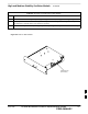
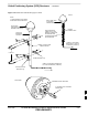
High and Medium Stability Oscillator Module – continued Table 9-4: Procedure to Install HSO or MSO Module Step Action 4 Install HSO Module cover panel by sliding its flange into the slot, closing, and latching it in place. 5 Notify operator that the HSO or MSO replacement procedure is completed. Have operator verify that old alarms have cleared and no new alarms are reported. 6 Install BTS front panel cover by setting it in place and pushing on the top and bottom simultaneously.
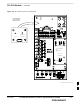
High and Medium Stability Oscillator Module – continued Figure 9-5: HSO or MSO Location HSO or MSO ti–cdma–wp–00286–v01–ildoc–ah 9 9-10 1X SC480 BTS Hardware Installation, Optimization/ATP, and FRU PRELIMINARY MAY 2004
Global Positioning System (GPS) Receivers Introduction The Compact BTS is configured with either Remote or RF Global Positioning System (GPS) receiver operation. For Remote GPS operation, the GPS receiver is located in a remotely–located GPS head. This head contains a GPS antenna, GPS receiver, and digital interface. The GPS receiver output signal from the RGPS head is applied to the Compact BTS. The received signal is routed to the CSA card.
Global Positioning System (GPS) Receivers – continued Table 9-5: Procedure to Remove RGPS Head Step Action 1 Notify operator that the RGPS Head replacement procedure is starting and that alarms can be expected. 2 Have the OMC–R operator verify the reference source configuration for the CSA. * IMPORTANT Before removing an RGPS Head that has a working RGPS receiver, have the OMC–R operator verify that the reference source for the CSA is configured for an HSO or MSO.
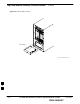
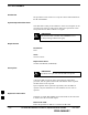
Global Positioning System (GPS) Receivers – continued Figure 9-6: RGPS Head and Mounting Pipe/Conduit VIEW A NOTE: 1.
RF–GPS Module Introduction The procedures in this section cover only the removal and installation of the RF–GPS Module. System Impact/Considerations If the RF–GPS is failing or has failed there will be an interruption in call processing. The entire site will be down during the replacement of this component unless an HSO or MSO is in support. IMPORTANT * The maximum loss of the RF cable CANNOT exceed 15 dB (assuming 25 dB antenna gain). Required Items Documents None Tools Star screw driver.
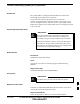
RF–GPS Module – continued Table 9-7: Procedure to Remove RF–GPS Step Action 1 Notify operator that the RF–GPS module replacement procedure is starting and that alarms can be expected. 2 Put on an ESD wrist strap or other approved grounding device. 3 At the rear of the BTS, disconnect RF–GPS cable from its SMA connector. See Figure 9-7. 4 Using a T20 bit, remove four M4 screws securing RF–GPS module to the CBIO Board.
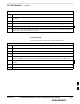
RF–GPS Module – continued Figure 9-7: RF–GPS Module SMA Connector Screw Holes Indicator RGPS Connector Screw Holes RF–GPS IN PWR RFGPS KIT NO. RFGPS SERIAL NO.
RF–GPS Module – continued Figure 9-8: RF–GPS Placement on CBIO Board RF–GPS plugged in and secured with four screws. PWR RFGPS KIT NO. RF–GPS IN RFGPS SERIAL NO. EXPANSION FRAME SYNC – OUT DAISY–CHAIN POWER SDCX POWER SDCX KIT NO. SDCX SERIAL NO.
Power Supply Module (PSM) Introduction The procedures in this section cover only the Power Supply Module (PSM). The PSM occupies the first slot in the CCP2 Shelf. System Impact/Consideration The PSM supplies DC power to the cards/modules of the CCP2 Shelf. If the module needed replacing it will cause an interruption in call processing. Required Items Documents None. Tools None.
Power Supply Module (PSM) – continued Replacement Procedure CAUTION This procedure requires working around circuitry that is extremely sensitive to Electrostatic Discharge (ESD). Wear a conductive, high impedance wrist strap during the procedure. Use appropriate safety measures. If desired, record the BTS and PSM serial number of the failed unit in Table 9-57 at the end of this chapter. Remove Power Supply Module Follow the procedure in Table 9-9 to remove the Power Supply Module.
Power Supply Module (PSM) – continued Table 9-10: Procedure to Install Power Supply Module Step Action 5 Push the latches in to engage the module with the backplane and lock the tabs. 6 Note that the LED turns red briefly, then green. Green indicates that it has passed all self–tests and is functional. 7 Notify the operator that the replacement procedure has been completed. Have the operator verify that the original alarms have cleared and that no new alarms are reported.
Clock Synchronization Alarms Card Introduction The procedures in this section cover only the Clock Synchronization Alarms (CSA) card. The CSA occupies the second slot in the CCP2 Shelf. System Impact/Considerations This replacement procedure does require some system downtime. Since there is no redundancy, call processing will be interrupted during the time of the replacement. Required Items Documents None. Tools None Replacement Item One CSA card.
Clock Synchronization Alarms Card – continued Table 9-11: Procedure to Remove CSA Module Step Action 2 Put on the ESD wrist strap or other approved grounding device. 3 If not already done, remove BTS front panel cover by grasping finger grooves at the top and bottom and pulling simultaneously. 4 Simultaneously press the locking tabs on both the top and bottom card latches 5 Pull the latches out to disengage the card from the shelf and slide the card out.
Clock Synchronization Alarms Card – continued Figure 9-10: Clock Synchronization and Alarm Card SYNC MONITOR Synchronization Monitor STA/ALM Status/Alarm LED FREQ.
Group Line Interface Card Introduction The procedures in this section cover only the Group Line Interface (GLI) 3 card. The GLI3 occupies the third slot in the CCP2 Shelf. System Impact/Considerations An interruption in call processing will occur if the GLI3 card is failing or fails. Prerequisite IMPORTANT * Coordinate this repair task with the OMC–R operator. Contact the OMC–R operator before performing the replacement procedure.
Group Line Interface Card – continued If desired, record the BTS and GLI3 serial number of the failed unit in Table 9-59 at the end of this chapter. Remove GLI3 Card Follow the procedure in Table 9-13 to remove the GLI3 card. Table 9-13: Procedure to Remove GLI3 Card Step Action n WARNING Disengaging the GLI3 from the CCP2 Shelf will cause the site to be shutdown due to the disruption in commnuication with the BBX and MCC cards.
Group Line Interface Card – continued Table 9-14: Procedure to Install GLI3 Card Step Action NOTE If the red ALARM LED remains ON, the card may not be fully seated in the backplane. Pull the card out about halfway, wait about two minutes before reseating. Perform steps 4 and 5. If the red LED turns back ON after the green LED turns OFF, a new failure condition exists and an alarm generated. 7 Notify operator that the GLI3 replacement procedure is completed.
Group Line Interface Card – continued Figure 9-11: Group Line Interface 3 Card BPR A BPR B AUX GLI RESET ALARM SPAN MMI STA ACT 9 MAY 2004 1X SC480 BTS Hardware Installation, Optimization/ATP, and FRU PRELIMINARY 9-27
Multi–Channel CDMA Card Introduction The procedures in this section cover only the Multi–Channel CDMA (MCC) cards. The MCC–1X cards occupy the fourth, fifth, and sixth slots (MCC 1, 2, & 3) in the CCP2 Shelf. If the MCC–DO card is in use, proceed to that section for more information later in this chapter. System Impact/Considerations If an MCC–1X card fails it will cause some interruption in call processing in the sense that not all calls will be handled.
Multi–Channel CDMA Card – continued Replacement Items S Up to 3 MCC–1X–16 cards (SGLN6117) S Up to 3 MCC–1X–32 cards (SGLN6050) S Up to 3 MCC–1X–48 cards (SGLN6051) S Up to 3 MCC–1X–64 cards (SGLN6052) (for Packet Backhaul) Prerequisite IMPORTANT * Coordinate this repair task with the OMC–R operator. Contact the OMC–R operator before performing the replacement procedure. Tell the operator that the MCC–1X card will be replaced and that alarms can be expected.
Multi–Channel CDMA Card – continued Table 9-16: Procedure to Remove MCC–1X Card Step Action 4 Simultaneously press the locking tabs on both the top and bottom card latches 5 Pull the latches out to disengage the card from the shelf and slide the card out. 6 Place MCC–1X card on/in an anti–static container or surface. Install MCC–1X Card Follow the procedure in Table 9-17 to install the MCC–1X card.
Multi–Channel CDMA Card – continued Figure 9-12: MCC 1X Card Power/Alarm LED PWR/ALM Active LED ACTIVE 9 MAY 2004 1X SC480 BTS Hardware Installation, Optimization/ATP, and FRU PRELIMINARY 9-31
Broadband Transceiver Card Introduction The procedures in this section cover only the Broad Band Transceiver 1X (BBX–1X) cards. These cards occupy the seventh and eighth slots (BBX 1 & 4) of the CCP2 Shelf. System Impact/ Considerations The Compact BTS is not configured for redundancy, so a failure of the BBX card will cause an interruption in call processing. It is still “hot–swappable” like its Macrocell counterparts. Once replacement is made, optimization procedures will have to be performed.
Broadband Transceiver Card – continued Required items Documents This manual for optimization and acceptance test procedures. Tools None Replacement Unit One or two 800 MHz BBX–1X card (SGLF4133) Prerequisite IMPORTANT * Coordinate this repair task with the OMC–R operator. Contact the OMC–R operator before performing the replacement procedure. Tell the operator that the BBX–1X card will be replaced and that alarms can be expected.
Broadband Transceiver Card – continued Remove BBX–1X Card Follow the procedure in Table 9-18 to remove the BBX–1X card. Table 9-18: Procedure to Remove BBX–1X Card Step Action n WARNING Due to a lack of redundancy, disengaging the BBX card(s) from the CCP2 Shelf will cause the site to be shutdown due to the disruption in communication with the GLI3 and loss of carrier. 1 Notify operator that the BBX–1X card replacement procedure is starting and that alarms can be expected.
Broadband Transceiver Card – continued Figure 9-13: BBX–1X Card PWR/ALM ACTIVE 9 MAY 2004 1X SC480 BTS Hardware Installation, Optimization/ATP, and FRU PRELIMINARY 9-35
Compact BTS Multi–Coupler Preselector Card Introduction The procedures in this section cover only the Multi–Coupler Preselector Card (cMPC). The cMPC occupies the ninth slot of the CCP2 Shelf. cMPC PWR/ALM LED States The cMPC has a dual color (green & red) power/alarm (PWR/ALM) status indicator LED located on its front panel. The card has its own alarm (fault) detection circuitry that controls what is displayed on the LED. Table 9-20 lists these states. Refer to Figure 9-14.
Compact BTS Multi–Coupler Preselector Card – continued Upon completion of the replacement procedure, have the OMC–R operator verify that old alarms are cleared and that no new ones are reported. Replacement Procedure CAUTION This procedure requires working around circuitry that is extremely sensitive to Electrostatic Discharge (ESD). Wear a conductive, high impedance wrist strap during the procedure. Use appropriate safety measures.
Compact BTS Multi–Coupler Preselector Card – continued Table 9-22: Procedure to Install cMPC Step Action 1 Put on an ESD wrist strap or other approved grounding device. 2 If not already done, remove new cMPC from its anti–static container. 3 Verify that the cMPC is set up for using 1 or 2 Compact PAs. See Figure 9-15. S For 1 PA, the jumper should be connected to the “Default” RF connector. S For 2 PAs, the jumper should be connected to the “Alternate” RF connector.
Compact BTS Multi–Coupler Preselector Card – continued Figure 9-14: Compact Multi–Coupler Preselector Card PWR/ALM POWER/ALARM LED 9 MAY 2004 1X SC480 BTS Hardware Installation, Optimization/ATP, and FRU PRELIMINARY 9-39
Compact BTS Multi–Coupler Preselector Card – continued Figure 9-15: Compact Multi–Coupler Preselector Card Jumper Connection P/O cMPC DEFAULT ALTERNATE Compact MPC shown is set for 1 Power Amplifier 9 9-40 1X SC480 BTS Hardware Installation, Optimization/ATP, and FRU PRELIMINARY MAY 2004
MCC Data Only (MCC–DO) Card Introduction The procedures in this section cover only the MCC Data Only (MCC–DO) card. If in use, this card utilizes MCC slots 1 and 2, with slot 3 containing an MCC–1X card or a filler panel. EV–DO FRU Information If there are conflicts between the procedures presented here and the material presented in 1xEV–DO Field Replaceable Unit (FRU) Procedures – 68P09257A99, the manual takes precedence.
MCC Data Only (MCC–DO) Card – continued Table 9-23: MCC–DO LED States LED Color Status –– OFF SPAN Both ENET and TAT link are down. NOTE: In the case of some spans on a given MCC–DO having Yellow alarms, and other spans having Red alarms, a Red Alarm state should be indicated. Required Items Documents None. Tools None. Replacement Items One MCC–Data Only card (SGLN6146) Prerequisite IMPORTANT * Coordinate this repair task with the OMC–R operator.
MCC Data Only (MCC–DO) Card – continued Table 9-24: Procedure to Remove MCC–DO Card Step Action 2 Put on the ESD wrist strap or other approved grounding device. 3 If not already done, remove BTS front panel cover by grasping finger grooves at the top and bottom and pulling simultaneously. 4 If not already done, label cables prior to disconnecting them from front panel connectors.
MCC Data Only (MCC–DO) Card – continued Figure 9-16: MCC–DO Card NOTE: 1.
Compact BTS Input and Output Board Introduction The procedures in this section cover only the removal and installation of the Compact BTS Input and Output (CBIO) Board. System Impact/Considerations If the CBIO board is failing or has failed there will be an interruption in call processing. The entire site will be down for replacement of this component. CBIO Indicators The CBIO Board has six indicators that provide status of several components of the BTS.
Compact BTS Input and Output Board – continued ISO LED The ISO LED indicates the status of the isolated DC voltage that is used for the customer inputs. This LED should always be ON, if the +5V supply to the CBIO Board is okay. If the LED is OFF, it indicates a problem on the CBIO Board. Required Items Documents None Tools Screwdriver with T20 star bit Replacement Items One CBIO Board. Prerequisite IMPORTANT * Coordinate this repair task with the OMC–R operator.
Compact BTS Input and Output Board – continued Table 9-26: Procedure to Remove CBIO Board Step Action n WARNING By pulling out the circuit breaker, power to the BTS will be interrupted, causing the BTS to go off line. 3 Disengage DC power to the BTS by pulling out the 20 A breaker at the rear of the BTS. 4 If possible, turn off DC power at the source. Verify that DC power source is OFF. 5 Disconnect all cabling to the BTS. 6 Put on the ESD wrist strap.
Compact BTS Input and Output Board – continued Table 9-27: Procedure to Install CBIO Board Step Action 8 Disengage from the ESD wrist strap. 9 Connect all external cabling. 10 Verify that DC power source is OFF before re–connecting to the BTS. Turn on DC power source. 11 Notify the operator know that the replacement procedure is completed, and that power up will begin shortly. 12 Allow the BTS to power up by pushing in the 20 A circuit breaker at the rear of the BTS.
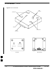
Compact BTS Input and Output Board – continued Figure 9-17: CBIO Board with SDCX Removed Screw to remove Screw to remove PWR RF–GPD IN SDCX Board or Cover Plate Removed Grasp holes with forefinger and thumb.
SDCX Module Introduction The procedures in this section cover only the removal and installation of the Synchronization Daisy–Chaining and eXpansion (SDCX) Module. System Impact/Considerations If the SDCX fails it will cause a disruption in call processing by upsetting the timing of the BTSs. Required Items Documents None Tools Star screw driver. Replacement Items One SDCX Module (SGLN6153) Prerequisite IMPORTANT * Coordinate this repair task with the OMC–R operator.
SDCX Module – continued Table 9-28: Procedure to Remove SDCX Step Action 3 Disconnect all cables from SDCX Module. 4 At the rear of the BTS, use a T20 screw driver to remove four M4 screws securing SDCX Module to the CBIO Board. See Figure 9-19. 5 Gently remove SDCX Module (disconnect it from the SDCX connector in the CBIO Board), and place it in/on an anti–static container or surface. Install SDCX Follow the procedure in Table 9-29 to install the SDCX.
SDCX Module – continued Figure 9-18: SDCX Module Expansion SDC Connectors RGPS TAIL Connector Used only if the site is configured for multiple BTSs.
SDCX Module – continued Figure 9-19: CBIO Board with SDCX PWR RF–GPS IN Remove screws EXPANSION FRAME SYNC – OUT DAISY–CHAIN POWER SDCX POWER SDCX KIT NO. SDCX SERIAL NO.
SDCX Module – continued Figure 9-20: CBIO Board with SDCX Removed PWR RF–GPD IN SDCX Board connector 9 ti–cdma–wp–00311–v01–ildoc–ah 9-54 1X SC480 BTS Hardware Installation, Optimization/ATP, and FRU PRELIMINARY MAY 2004
RF Filter Tray Introduction The procedures in this section cover only the removal and installation of the RF Filter Tray. System Impact/Considerations If either of the filters on the tray is failing or has failed there will be an interruption in call processing. The entire site will be down for replacement of this component.
RF Filter Tray – continued NOTE To perform the following procedure, the BTS must be removed from the Mounting Plate. Table 9-30: Preparation Procedure for Removing the Filter Tray Step Action 1 Notify operator that the Filter Kit replacement procedure is starting and that alarms can be expected. 2 Perform the Site Shutdown procedure in Table 10-2. 3 Remove 3 M6 screws and washers securing BTS to Mounting Plate.
RF Filter Tray – continued Table 9-31: Procedure to Remove Filter Tray Kit SGLF4152 Step Action 1 Perform the preparation procedure described in Table 9-30. 2 Using a screwdriver with T20 star bit, remove two screws securing the Filter Tray Assembly to the chassis.
RF Filter Tray – continued Figure 9-21: cMPC Cable Clip TOWARDS FRONT OF BTS TOWARDS REAR OF BTS SLOT6 SLOT1 cMPC Cable Clip Installation Procedure Follow the procedure in Table 9-33 to install the cMPC cable clip. Table 9-33: Procedure to Install cMPC Cable Clip Step Action 1 Properly position cables in clip (order defined in installation procedure).
RF Filter Tray – continued Table 9-34: Procedure to Install Filter Tray Kit SGLF4152 Step 4 Action Connect cables to the RFL–MAIN, RFL–DIV, and FWD–DIV connectors at the inside rear of the BTS, respectively. Use a 5/16–in wrench to secure cables to connectors. Torque to 1 N–M. NOTE Cables have two heat shrink sleeves with a slight separation between them. The cMPC cable clip slides into this separation to hold the cables in place.
RF Filter Tray – continued Table 9-34: Procedure to Install Filter Tray Kit SGLF4152 Step Action 19 Connect all external cabling. 20 Verify that DC power source is OFF before re–connecting to the BTS. Turn on DC power source. 21 Notify the operator know that the replacement procedure is completed, and that power up will begin shortly. 22 Allow the BTS to power up by pushing in the 20 A circuit breaker at the rear of the BTS. 23 Perform the Site Startup procedure in Table 10-5.
RF Filter Tray – continued Figure 9-22: Filter Tray Connectors and Cable Part Numbers RX DIV Cable PN 3086617X05 RFL–DIV Cable PN 3086617X08 FWD–DIV Cable PN 3086617X18 RFL–MAIN Cable PN 3086617X07 RX MAIN Cable PN 3086617X04 Front View Input Connectors RX DIV Cable PN 3086617X02 RX MAIN Cable PN 3086617X03 Rear View Output Connectors Filter Tray Kit SGLN6223 Removal Procedure Follow the procedure in Table 9-35 to remove the Filter Tray Kit (SGLN6223).
RF Filter Tray – continued Table 9-35: Procedure to Remove Filter Tray Kit SGLN6223 Step Action 3 Disconnect the RF cables (Input) in the following order: – RX MAIN connector (blue) from RX MAIN connector RX DIV connector (green) RX RFL–DIV connector (green) RX FWD–DIV connector (green) See Figure 9-23 4 Hold cables to one side and slide out filter tray to expose cable attached to rear connector (Output) of the RX DIV filter. 5 Disconnect RX DIV (Output) cable (green).
RF Filter Tray – continued Install Filter Tray Kit SGLN6223 Follow the procedure in Table 9-36 to install the Filter Tray. Refer to Figure 9-22. Table 9-36: Procedure to Install Filter Tray Kit SGLN6223 Step 1 Action Put on an ESD wrist strap or other approved grounding device. Ensure that wrist strap is properly grounded. NOTE Do not attach grounding devices to BTS chassis.
RF Filter Tray – continued Table 9-36: Procedure to Install Filter Tray Kit SGLN6223 Step Action 12 Install the rear right side vent panel. Ensure that the clip end faces the front of the BTS or towards the left. 13 Install the front right side vent panel. Ensure that the clip end faces the front of the BTS or towards the left. 14 Make sure the vent panels are flush with the side of the BTS. 15 Install CBIO Board following the procedure in Table 9-27.
RF Filter Tray – continued Table 9-37: Procedure to Remove Filter Tray Kit SGLN6222 Step Action 1 Perform the preparation procedure described in Table 9-30. 2 Disconnect the cables in the following order: – RX MAIN connector (X35, blue) from RX MAIN (X04, blue) connector RX DIV connector (X36, green) from RX DIV (X05, green) connector See Figure 9-24.
RF Filter Tray – continued Table 9-38: Procedure to Install Filter Tray Kit SGLN6222 Step Action 8 Install the front right side vent panel. Ensure that the clip end faces the front of the BTS or towards the left. 9 Make sure the vent panels are flush with the side of the BTS. 10 Install circuit cards and modules, ensure they are seated properly. 11 Install HSO Module cover panel by sliding its flange into the slot, closing, and latching it in place. 12 Disengage from the ESD wrist strap.
Compact Combined Linear Power Amplifier Introduction The procedures in this section cover only the removal and installation of the Compact Combined Linear Power Amplifier (cCLPA). System Impact/Considerations If the cCLPA is failing or has failed there will be an interruption in call processing. While the BTS itself may be operational, there may not be reception or transmission depending on the fault.
Compact Combined Linear Power Amplifier – continued Table 9-39: Procedure to Remove cCLPA Step Action 3 Turn off DC power to the cCLPA. For Outdoor configuration disengage the PDE circuit breaker to the cCLPA being removed. 4 Use a screwdriver with a T20 star bit to remove 8 screws securing I/O Board cover to the cCLPA. 5 Loosen screws securing DC power to the I/O Board DC connector. 6 Disconnect BTS Data Cable from the I/O Board. 7 Disconnect ground cable from the cCLPA.
Compact Combined Linear Power Amplifier – continued Figure 9-25: Compact Combined Linear Power Amplifier ti–cdma–wp–00300–v01–ildoc–ah 9 MAY 2004 1X SC480 BTS Hardware Installation, Optimization/ATP, and FRU PRELIMINARY 9-69
TME Power Distribution Assembly Introduction The procedures in this section cover only the removal and installation of the TME Power Distribution Assembly (PDA) System Impact/Considerations If the PDA is failing or has failed there will be an interruption in call processing. Power to the BTS and 1U unit will be interrupted.
TME Power Distribution Assembly – continued Figure 9-26: PDA Location –48VDC PDA ti–cdma–wp–00262–v03–ildoc–ah Replacement Procedure If desired, record the BTS and PDA serial number of the failed unit in Table 9-68 at the end of this chapter. Remove PDA Follow the procedure in Table 9-41 to remove the PDA. See Figure 9-26 or Figure 9-28. Table 9-41: Procedure to Remove PDA Step Action 1 Notify operator that the PDA replacement procedure is starting and that alarms can be expected.
TME Power Distribution Assembly – continued Table 9-41: Procedure to Remove PDA Step Action 8 Gently pull out PDA far enough to disconnect cables at the rear. 9 Remove PDA.
TME Power Distribution Assembly – continued Install PDA Follow the procedure in Table 9-42 to install the PDA. See Figure 9-26 or Figure 9-28. Table 9-42: Procedure to Install PDA Step Action 1 Hold PDA near its slot in the TME and connect the cables (previously disconnected) to the rear of the PDA. 2 Slide PDA in and secure to TME chassis by tightening the captive screws. 3 Place ground lug on ground studs of the PDA and secure using two M6 nuts and washers. Torque nuts to 3.4 N–M (30 in–lbs).
TME Power Distribution Assembly – continued Figure 9-28: Power Distribution Assembly for +27VDC Captive Screw TME Circuit Breaker (Rocker Style) 1U Circuit Breaker +27 VDC Connector Socket Captive Screw Ground Location FRONT ti–cdma–wp–00348–v01–ildoc–ah HMS Connection BTS / 1U Connection TME Door Alarm Connection REAR ti–cdma–wp–00346–v01–ildoc–ah 9 9-74 1X SC480 BTS Hardware Installation, Optimization/ATP, and FRU PRELIMINARY MAY 2004
Heat Management System Introduction The procedures in this section cover only the removal and installation of the Heat Management System (HMS) System Impact/Considerations If the HMS is failing or has failed there will be an interruption in call processing. It is recommended that power be disengaged from the TME.
Heat Management System – continued Contact the OMC–R operator before performing the replacement procedure. Tell the operator that the HMS or its components will be replaced and that alarms can be expected. Upon completion of the replacement procedure, have the OMC–R operator verify that old alarms are cleared and that no new ones are reported.
Heat Management System – continued Table 9-43: Procedure to Remove HMS Step Action 1 Notify operator that the HMS replacement procedure is starting and that alarms can be expected. 2 Turn off DC power to the TME. 3 Unlock and remove external lock 4 Use key to unlock HMS draw latch door. 5 Turn latches and slowly swing open HMS. ! CAUTION Be aware of the heater elements, they will be hot to the touch if they have been in recent use.
Heat Management System – continued Heater Element Replacement Procedure This information is still under consideration at this time. Updated information will be supplied at a later date. If desired, record the TME, HMS, and HMS Heater Elements serial number of the failed unit in Table 9-70 at the end of this chapter. Perform the procedure in Table 9-45 to remove the Heater Elements. Table 9-45: Procedure to Replace Heater Elements Step 1 Action Perform the HMS removal procedure described in Table 9-43.
Heat Management System – continued Figure 9-30: HMS Heater Elements NOTE: 1. 8 point microdocument 2. 8 point microdocument 8 pt. Left Aligned text 8 pt. Right Aligned Text 8 pt. Centered Text HMS Controller Replacement Procedure This information is still under consideration at this time. Updated information will be supplied at a later date. If desired, record the TME, HMS, and HMS Controller serial number of the failed unit in Table 9-71 at the end of this chapter.
Heat Management System – continued Perform the procedure in Table 9-48 to install the HMS Controller. Table 9-48: Procedure to Install HMS Controller Step Action 1 2 3 4 5 Perform the procedure in Table 9-44 to install the HMS. Figure 9-31: HMS Controller ti–cdma–wp–00263–v01–ildoc–ah Blower Fan Replacement Procedure 9 This information is still under consideration at this time. Updated information will be supplied at a later date.
Heat Management System – continued Table 9-49: Procedure to Replace Blower Fan Step 1 Action Perform the procedure in Table 9-43 to remove the HMS. 2 3 4 5 Blower Fan Installation Procedure This information is still under consideration at this time. Updated information will be supplied at a later date. Perform the procedure in Table 9-48 to install the Blower Fan. Table 9-50: Procedure to Install Blower Fan Step Action 1 2 3 4 5 Perform the procedure in Table 9-44 to install the HMS.
Heat Management System – continued Figure 9-32: Blower Fan NOTE: 1. 8 point microdocument 2. 8 point microdocument 8 pt. Left Aligned text 8 pt. Right Aligned Text 8 pt.
Thermal Management Enclosure Introduction The procedures in this section cover only the removal and installation of the Thermal Management Enclosure (TME). System Impact/Considerations If the TME enclosure has been damaged it will no longer environmetally protect the BTS. Thus, an interruption in call processingwill occur while the TME is replaced.
Thermal Management Enclosure – continued Table 9-51: Procedure to Remove TME Step Action 3 Disengage circuit breaker on the affected cCLPAs. 4 Use the key to unlock both doors of the TME. 5 Disengage TME PDA circuit breakers by pulling them out. 6 At the rear of the BTS disconnect antenna cables from BTS to TME. 7 If not already done, label individual cables as they are disconnected from the rear of the BTS. 8 Remove cover and disconnect DC power cables from BTS.
Thermal Management Enclosure – continued Table 9-52: Procedure to Install TME Step Action 5 Insert cables from conduit up through their respective access holes and connect to the BTS. 6 Tighten conduit hubs. 7 Use a screw driver and two screws to secure the ground lug to the BTS. 8 Connect antenna cables from BTS to TME. 9 Connect all cabling to connectors on bottom of the TME. 10 Install DC power wires to BTS, use a screwdriver to tighten screws holding wires.
Power Distribution Enclosure Introduction The procedures in this section cover only the removal and installation of the Powerl Distribution Enclosure (PDE). System Impact/Considerations If the PDE enclosure has been damaged it will no longer environmetally protect the AC–to–DC power converter circuitry. Thus, an interruption in call processing will occur while the PDE is replaced. Replacement Procedure Consult the manufacturer’s Field Replacement Unit (FRU) guide for removal and replacement information.
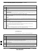
Master Item Number Failure List Introduction The Master Item Number Failure List is provided as a means of keeping a written record of the units that failed for any particular BTS or BTSes. The list is for logistical purposes only. For the BTS Fan Module, use Table 9-53. Table 9-53: Fan Module Item Number List Item Number BTS Number Fan Module Number For the HSO/MSO Module, use Table 9-54.
Master Item Number Failure List – continued For the PSM, use Table 9-57. Table 9-57: PSM Item Number List Item Number BTS Number PSM Number For the CSA Card, use Table 9-58. Table 9-58: CSA Card Item Number List Item Number BTS Number CSA Card For the GLI3 Card, use Table 9-59. Table 9-59: GLI3 Card Item Number List Item Number BTS Number GLI3 Card For the MCC–1X, use Table 9-60.
Master Item Number Failure List – continued For the BBX–1X, use Table 9-61. Table 9-61: BBX–1X Card Item Number List Item Number BTS Number BBX 1 (SGLF4136) BBX 4 (SGLF4136) For the cMPC, use Table 9-62. Table 9-62: Compact MPC Item Number List Item Number BTS Number Compact MPC Number For the MCC–DO card, use Table 9-63. Table 9-63: MCC–DO Card Item Number List Item Number BTS Number MCC–Data Only Card For the CBIO Board, use Table 9-64.
Master Item Number Failure List – continued For the Filter Tray, use Table 9-66. Table 9-66: Filter Tray Kit Item Number List Item Number BTS Number Filter Tray Kit (SGLF4152) Filter Tray Kit (SGLN6223) Filter Tray Kit (SGLN6222) For the cCLPA, use Table 9-67. Table 9-67: cCLPA Item Number List Item Number BTS Number cCLPA #1 (If used) cCLPA #2 (If used) For the TME PDA, use Table 9-68. Table 9-68: TME PDA Item Number List Item Number TME Number PDA For the TME HMS, use Table 9-69.
Master Item Number Failure List – continued For the TME HMS Heater Elements, use Table 9-70. Table 9-70: TME HMS Heater Element Item Number List Item Number TME Number HMS Number Heater Element For the TME HMS Controller, use Table 9-71. Table 9-71: TME HMS Controller Item Number List Item Number TME Number HMS Number HMS Controller Number For the TME HMS Blower Fan, use Table 9-72.
Master Item Number Failure List – continued Notes 9 9-92 1X SC480 BTS Hardware Installation, Optimization/ATP, and FRU PRELIMINARY MAY 2004
Chapter 10: Reference Procedures Performed At OMC–R Table of Contents Reference Procedures Performed At OMC–R . . . . . . . . . . . . . . . . . . . . . . . . . . Introduction . . . . . . . . . . . . . . . . . . . . . . . . . . . . . . . . . . . . . . . . . . . . . . 10-1 10-1 Accessing OMC–R CLI Window . . . . . . . . . . . . . . . . . . . . . . . . . . . . . . . . . . . . Accessing OMC–R CLI Window . . . . . . . . . . . . . . . . . . . . . . . . . . . . . 10-2 10-2 Circuit BTS Shut Down Procedures . .
Table of Contents – continued Notes 10 1X SC480 BTS Hardware Installation, Optimization/ATP, and FRU PRELIMINARY MAY 2004
Reference Procedures Performed At OMC–R Introduction The procedures in this chapter are referenced during various FRU replacement procedures and are performed by the OMC–R operator.
Accessing OMC–R CLI Window Accessing OMC–R CLI Window Many of the FRU procedures require the OMC–R operator to manipulate BTS logical devices. This is achieved via UNO or the OMC–R (Operations and Maintenance Center – Radio) Command Line Interface (CLI). The operator enters commands via UNO or OMC–R CLI. IMPORTANT * Should there be any issues which affect UNO or the OMC–R CLI operations, command dependent replacement procedures cannot be performed.
Circuit BTS Shut Down Procedures Shut Down Site Signaling Functions for a Circuit BTS If a complete site shutdown is required for the FRU replacement, follow the procedure in Table 10-2 to disable the circuit BTS site. CAUTION This site shut down procedure takes a BTS out–of–service (OOS), but does not affect other BTSs. To minimize system impact, it may be advisable (but not necessary) to perform this procedure during a maintenance window.
Circuit BTS Shut Down Procedures – continued Table 10-2: Shut Down Site Signaling Functions Procedure For a Circuit BTS n Step Action NOTE The REDIRECT command is used to redirect subscribers to an 800 MHz analog site or to invoke the REDIRECT2 command which is then used to redirect subscribers to a different CDMA carrier frequency. REDIRECT2 is the preferred command if an alternate CDMA carrier is available. * IMPORTANT Record the values shown in the following system display response.
Circuit BTS Shut Down Procedures – continued Table 10-2: Shut Down Site Signaling Functions Procedure For a Circuit BTS n Step Action NOTE This step edits the REDIRECT parameters so that the Global Service Redirect Message to be broadcast on the paging channel redirects all subscribers away from the BTS and onto a different BTS or system. 4 Enter the following command at the prompt: omc–000000>EDIT BTS– REDIRECT! The system prompts you to enter each command parameter value one at a time.
Circuit BTS Shut Down Procedures – continued Table 10-2: Shut Down Site Signaling Functions Procedure For a Circuit BTS n Step Action 5 View the status of the signaling REDIRECT parameters to verify that the applicable BTS is ready for global redirect. omc–000000>DISPLAY BTS– REDIRECT Ensure that the values in the system display response match the values input in Step 4 (see example below).
Circuit BTS Shut Down Procedures – continued Table 10-2: Shut Down Site Signaling Functions Procedure For a Circuit BTS n Step Action NOTE This step edits the REDIRECT2 parameters so that the Global Service Redirect Message to be broadcast on the paging channel redirects all subscribers away from the BTS with the failed equipment and onto a CDMA channel at a neighbor site.
Circuit BTS Shut Down Procedures – continued Table 10-2: Shut Down Site Signaling Functions Procedure For a Circuit BTS n Step 10 Action View the existing congestion control parameters for all carriers equipped for the BTS by entering the following command at the prompt: omc–000000>DISPLAY BTS– CONGESTCONF Observe the following typical system display response for a BTS: CARRIER (bts#–sector#–carrier#) ––––––––––––––––––––––– 1–1–1 SET ––– 1 NEWCALL ALARMFLAG ––––––––– ENABLE REG ALARMFLAG ––
Circuit BTS Shut Down Procedures – continued Table 10-2: Shut Down Site Signaling Functions Procedure For a Circuit BTS n Step Action 14 Wait three minutes to allow any active calls to terminate.
Circuit BTS Shut Down Procedures – continued Table 10-3: Shut Down Sector Signaling Functions Procedure For a Circuit BTS n Step Action * IMPORTANT It is recommended that you redirect subscribers to another sector/carrier and then wait for any active calls to terminate before disabling the sector/carrier. 2 If you want to redirect subscribers and then wait for any active calls to terminate before disabling the sector/carrier, go to step 3.
Circuit BTS Shut Down Procedures – continued Table 10-3: Shut Down Sector Signaling Functions Procedure For a Circuit BTS n Step Action NOTE This step edits the REDIRECT parameters so that the Global Service Redirect Message to be broadcast on the paging channel redirects all subscribers away from the sector with the failed equipment and onto a different sector, BTS, or system.
Circuit BTS Shut Down Procedures – continued Table 10-3: Shut Down Sector Signaling Functions Procedure For a Circuit BTS n Step 5 Action View the status of the sector signaling REDIRECT parameters to verify that the applicable sector is ready for global redirect. omc–000000>DISPLAY SECTOR–– REDIRECT Ensure that the values in the system display response match the values input in Step 4 (see example below).
Circuit BTS Shut Down Procedures – continued Table 10-3: Shut Down Sector Signaling Functions Procedure For a Circuit BTS n Step Action NOTE This step edits the REDIRECT2 parameters so that the Global Service Redirect Message to be broadcast on the paging channel redirects all subscribers away from the sector with the failed equipment and onto a CDMA channel at a neighbor sector/site.
Circuit BTS Shut Down Procedures – continued Table 10-3: Shut Down Sector Signaling Functions Procedure For a Circuit BTS n Step 10 Action View the existing congestion control parameters for all carriers equipped for the applicable sector by entering the following command at the prompt: omc–000000>DISPLAY SECTOR–– CONGESTCONF Observe the following typical system display response for sector 2: CARRIER (bts#–sector#–carrier#) ––––––––––––––––––––––– 1–1–1 SET ––– 1 NEWCALL ALARMFLAG –––––
Circuit BTS Shut Down Procedures – continued Table 10-3: Shut Down Sector Signaling Functions Procedure For a Circuit BTS n Step 13 Action Display the status of all devices at the BTS by entering the following command at the prompt: omc–000000>DISPLAY BTS– STATUS Observe the following typical system response: DEVICE –––––––––––––––––– BTS–1 BTSSPAN–1–1 BTSLINK–1–1 GLI–1–1 CSA–1–1 BBX–1–1 BBX–1–2 MCC–1–1 CBSC –––– 1 1 1 1 1 1 1 1 STATUS –––––– INS INS INS INS–ACTIVE INS_ACTIVE INS–ACTIVE INS–ST
Circuit BTS Shut Down Procedures – continued Shut Down Carrier Signaling Functions for a Circuit BTS If a carrier shutdown is required for the FRU replacement and the site is currently under CBSC control, follow the procedure in Table 10-4 to disable the carrier at a circuit BTS. CAUTION This carrier shut down procedure takes a carrier out–of–service (OOS) but does not affect the other carriers.
Circuit BTS Shut Down Procedures – continued Table 10-4: Shut Down Carrier Signaling Functions Procedure For a Circuit BTS n Step Action NOTE The REDIRECT command is used to redirect subscribers to an 800 MHz analog site or to invoke the REDIRECT2 command which is then used to redirect subscribers to a different CDMA carrier frequency. REDIRECT2 is the preferred command if an alternate CDMA carrier is available. * IMPORTANT Record the values shown in the following system display response.
Circuit BTS Shut Down Procedures – continued Table 10-4: Shut Down Carrier Signaling Functions Procedure For a Circuit BTS n Step Action NOTE This step edits the REDIRECT parameters so that the Global Service Redirect Message to be broadcast on the paging channel redirects subscribers assigned to the sector carrier away from the carrier/sector with the failed equipment and onto a different carrier, sector, BTS, or system.
Circuit BTS Shut Down Procedures – continued Table 10-4: Shut Down Carrier Signaling Functions Procedure For a Circuit BTS n Step 5 Action View the status of the carrier signaling redirect parameters to verify that the carrier is ready for maintenance. omc–000000>DISPLAY CARRIER––– REDIRECT Ensure that the values in the system display response match the values input in Step 4 (see example below).
Circuit BTS Shut Down Procedures – continued Table 10-4: Shut Down Carrier Signaling Functions Procedure For a Circuit BTS n Step Action NOTE This step edits the redirect parameters so that the Global Service Redirect Message to be broadcast on the paging channel redirects all subscribers away from the carrier with the failed equipment and onto a different CDMA carrier frequency.
Circuit BTS Shut Down Procedures – continued Table 10-4: Shut Down Carrier Signaling Functions Procedure For a Circuit BTS n Step 12 Action View the existing congestion control parameters for the applicable carrier equipped for a specific sector by entering the following command at the prompt: omc–000000>DISPLAY CARRIER––– CONGESTCONF Observe the following typical system display response for carrier 1, sector 2: CARRIER (bts#–sector#–carrier#) ––––––––––––––––––––––– 146–2–1 SE
Circuit BTS Shut Down Procedures – continued Table 10-4: Shut Down Carrier Signaling Functions Procedure For a Circuit BTS n Step 15 Action Display the status of all devices at the BTS by entering the following command at the prompt: omc–000000>DISPLAY BTS– STATUS Observe the following typical system response: DEVICE –––––––––––––––––– BTS–1 BTSSPAN–1–1 BTSLINK–1–1 MGLI–1–1 CSA–1–1 BBX–1–1 BBX–1–2 MCC–1–1 MCC–1–2 MCC–1–3 CBSC –––– 1 1 1 1 1 1 1 1 1 1 STATUS –––––– INS INS INS INS–ACTIVE INS_AC
Circuit BTS Start–Up Procedures Restore Site Signaling Operations for a Circuit BTS Restore site signaling operations according to the procedure in Table 10-5. Table 10-5: Restore Site Signaling Operations Procedure For a Circuit BTS n Step Action AT THE OMCR 1 Open a CLI window. Refer to the Accessing OMC–R CLI Window section on page 10-2.
Circuit BTS Start–Up Procedures – continued Table 10-5: Restore Site Signaling Operations Procedure For a Circuit BTS n Step Action NOTE In this step, you will change the value of the Global Service Redirection Flag (GLOBALREDIRECT) in the congestion control parameters so that the Global Service Redirect Message is only broadcast on the sector paging channel when there is traffic congestion in the sector.
Circuit BTS Start–Up Procedures – continued Table 10-5: Restore Site Signaling Operations Procedure For a Circuit BTS n Step Action * IMPORTANT In this step, use the values recorded in step 3 of the shut down site signaling functions procedure for a circuit BTS Table 10-2 to answer the prompts for the EDIT BTS REDIRECT command; except for record type enter 2. NOTE This step shows the entry of initial standard values which is consistent with the original example; except record type must be 2.
Circuit BTS Start–Up Procedures – continued Restore Sector Signaling Operations for a Circuit BTS Restore sector signaling operations according to the procedure in Table 10-6. Table 10-6: Restore Sector Signaling Operations Procedure For a Circuit BTS n Step Action AT THE OMCR 1 Open a CLI window. Refer to the Accessing OMCR CLI Window section on page 10-2.
Circuit BTS Start–Up Procedures – continued Table 10-6: Restore Sector Signaling Operations Procedure For a Circuit BTS n Step Action NOTE In this step, you will change the value of the Global Service Redirection Flag (GLOBALREDIRECT) in the congestion control parameters so that the Global Service Redirect Message is only broadcast on the sector paging channel when there is traffic congestion in the sector.
Circuit BTS Start–Up Procedures – continued Table 10-6: Restore Sector Signaling Operations Procedure For a Circuit BTS n Step Action * IMPORTANT In this step, use the values recorded in step 3 of the shut down sector signaling functions procedure for a circuit BTS Table 10-2 to answer the prompts for the EDIT SECTOR REDIRECT command; except for record type enter 2. NOTE This step shows the entry of initial standard values which is consistent with the original example; except record type must be 2.
Circuit BTS Start–Up Procedures – continued Restore Carrier Signaling Operations for a Circuit BTS Restore carrier signaling operations according to the procedure in Table 10-7. Table 10-7: Restore Carrier Signaling Operations Procedure For a Circuit BTS n Step Action 1 Open a CLI window. Refer to the Accessing OMCR CLI Window section on page 10-2.
Circuit BTS Start–Up Procedures – continued Table 10-7: Restore Carrier Signaling Operations Procedure For a Circuit BTS n Step Action NOTE In this step, you will change the value of the Global Service Redirection Flag (GLOBALREDIRECT) in the congestion control parameters so that the Global Service Redirect Message is only broadcast on the sector paging channel of a specific carrier when there is traffic congestion in the carrier/sector.
Circuit BTS Start–Up Procedures – continued Table 10-7: Restore Carrier Signaling Operations Procedure For a Circuit BTS n Step Action * IMPORTANT In this step, use the values recorded in step 3 of the shut down carrier signaling functions procedure for a circuit BTS Table 10-4 to answer the prompts for the EDIT CARRIER REDIRECT command; except for record type enter 2. NOTE This step shows the entry of initial standard values which is consistent with the original example; except record type must be 2.
Packet BTS Shut Down Procedures Shut Down Site Signaling Functions for a Packet BTS If a complete site shutdown is required for the FRU replacement, follow the procedure in Table 10-8 to disable the packet BTS site. CAUTION This site shut down procedure takes a BTS out–of–service (OOS), but does not affect the other BTSs. To minimize system impact, it may be advisable (but not necessary) to perform this procedure during a maintenance window.
Packet BTS Shut Down Procedures – continued Table 10-8: Shut Down Site Signaling Functions Procedure For a Packet BTS n Step Action AT THE OMC–R 1 Open a CLI window. Refer to the Accessing OMC–R CLI Window section on page 10-2. * IMPORTANT It is recommended that you redirect subscribers to another site/carrier and then wait for any active calls to terminate before locking/disabling the BTS.
Packet BTS Shut Down Procedures – continued Table 10-8: Shut Down Site Signaling Functions Procedure For a Packet BTS n Step Action NOTE This step edits the REDIRECT parameters so that the Global Service Redirect Message to be broadcast on the paging channel redirects all subscribers away from the BTS and onto a different BTS or system. 4 Enter the following command at the prompt: omc–000000>EDIT BTS– REDIRECT! The system prompts you to enter each command parameter value one at a time.
Packet BTS Shut Down Procedures – continued Table 10-8: Shut Down Site Signaling Functions Procedure For a Packet BTS n Step Action 5 View the status of the signaling REDIRECT parameters to verify that the applicable BTS is ready for global redirect. omc–000000>DISPLAY BTS– REDIRECT Ensure that the values in the system display response match the values input in Step 4 (see example below).
Packet BTS Shut Down Procedures – continued Table 10-8: Shut Down Site Signaling Functions Procedure For a Packet BTS n Step Action NOTE This step edits the REDIRECT2 parameters so that the Global Service Redirect Message to be broadcast on the paging channel redirects all subscribers away from the BTS with the failed equipment and onto a CDMA channel at a neighbor site.
Packet BTS Shut Down Procedures – continued Table 10-8: Shut Down Site Signaling Functions Procedure For a Packet BTS n Step 10 Action View the existing congestion control parameters for all carriers equipped for the BTS by entering the following command at the prompt: omc–000000>DISPLAY BTS– CONGESTCONF Observe the following typical system display response for a BTS: CARRIER (bts#–sector#–carrier#) ––––––––––––––––––––––– 146–1–1 SET ––– 1 NEWCALL ALARMFLAG ––––––––– ENABLE REG ALARMFLAG ––
Packet BTS Shut Down Procedures – continued Table 10-8: Shut Down Site Signaling Functions Procedure For a Packet BTS n Step 13 Action Display the status of all devices at the BTS by entering the following command at the prompt: omc–000000>DISPLAY BTS– STATUS Record the system response for all devices that are OOS_AUTOMATIC. This information will be used for later reference when restoring site signaling operations.
Packet BTS Shut Down Procedures – continued Shut Down Sector Signaling Functions for a Packet BTS If a sector shutdown is required for the FRU replacement and the site is currently under CBSC control, follow the procedure in Table 10-9 to disable the sector at a packet BTS. CAUTION This sector shut down procedure takes a sector out–of–service (OOS), but does not affect the other sectors.
Packet BTS Shut Down Procedures – continued Table 10-9: Shut Down Sector Signaling Functions Procedure For a Packet BTS n Step Action AT THE OMC–R 1 Open a CLI window. Refer to the Accessing OMC–R CLI Window section on page 10-2. * IMPORTANT It is recommended that you redirect subscribers to another sector/carrier and then wait for any active calls to terminate before locking/disabling the sector/carrier.
Packet BTS Shut Down Procedures – continued Table 10-9: Shut Down Sector Signaling Functions Procedure For a Packet BTS n Step Action NOTE This step edits the REDIRECT parameters so that the Global Service Redirect Message to be broadcast on the paging channel redirects all subscribers away from the sector with the failed equipment and onto a different sector, BTS, or system.
Packet BTS Shut Down Procedures – continued Table 10-9: Shut Down Sector Signaling Functions Procedure For a Packet BTS n Step 5 Action View the status of the sector signaling REDIRECT parameters to verify that the applicable sector is ready for global redirect. omc–000000>DISPLAY SECTOR–– REDIRECT Ensure that the values in the system display response match the values input in Step 4 (see example below).
Packet BTS Shut Down Procedures – continued Table 10-9: Shut Down Sector Signaling Functions Procedure For a Packet BTS n Step Action NOTE This step edits the REDIRECT2 parameters so that the Global Service Redirect Message to be broadcast on the paging channel redirects all subscribers away from the sector with the failed equipment and onto a CDMA channel at a neighbor sector/site.
Packet BTS Shut Down Procedures – continued Table 10-9: Shut Down Sector Signaling Functions Procedure For a Packet BTS n Step 10 Action View the existing congestion control parameters for all carriers equipped for the applicable sector by entering the following command at the prompt: omc–000000>DISPLAY SECTOR–– CONGESTCONF Observe the following typical system display response for sector 1: CARRIER (bts#–sector#–carrier#) ––––––––––––––––––––––– 146–2–1 SET ––– 1 NEWCALL ALARMFLAG –––––
Packet BTS Shut Down Procedures – continued Table 10-9: Shut Down Sector Signaling Functions Procedure For a Packet BTS n Step Action NOTE SHUTDOWN and REDIRECT both prevent future calls from being originated on the targeted resource, but only SHUTDOWN waits indefinitely for the calls to terminate. When the resource becomes idle, SHUTDOWN automatically transitions the resource to the locked/disabled state. 14 15 16 If you redirected subscribers but do not want to use SHUTDOWN, go to step 15.
Packet BTS Shut Down Procedures – continued Shut Down Carrier Signaling Functions for a Packet BTS If a carrier shutdown is required for the FRU replacement and the site is currently under CBSC control, follow the procedure in Table 10-10 to disable the carrier at a packet BTS. CAUTION This carrier shut down procedure takes a carrier out–of–service (OOS) but does not affect the other carriers.
Packet BTS Shut Down Procedures – continued Table 10-10: Shut Down Carrier Signaling Functions Procedure For a Packet BTS n Step Action AT THE OMC–R 1 Open a CLI window. Refer to the Accessing OMC–R CLI Window section on page 10-2. * IMPORTANT It is recommended that you redirect subscribers to another sector/carrier and then wait for any active calls to terminate before locking/disabling the sector/carrier.
Packet BTS Shut Down Procedures – continued Table 10-10: Shut Down Carrier Signaling Functions Procedure For a Packet BTS n Step Action NOTE This step edits the REDIRECT parameters so that the Global Service Redirect Message to be broadcast on the paging channel redirects subscribers assigned to the sector carrier away from the carrier/sector with the failed equipment and onto a different carrier, sector, BTS, or system.
Packet BTS Shut Down Procedures – continued Table 10-10: Shut Down Carrier Signaling Functions Procedure For a Packet BTS n Step 5 Action View the status of the carrier signaling redirect parameters to verify that the carrier is ready for maintenance. omc–000000>DISPLAY CARRIER––– REDIRECT Ensure that the values in the system display response match the values input in Step 4 (see example below).
Packet BTS Shut Down Procedures – continued Table 10-10: Shut Down Carrier Signaling Functions Procedure For a Packet BTS n Step Action NOTE This step edits the redirect parameters so that the Global Service Redirect Message to be broadcast on the paging channel redirects all subscribers away from the carrier with the failed equipment and onto a different CDMA carrier frequency.
Packet BTS Shut Down Procedures – continued Table 10-10: Shut Down Carrier Signaling Functions Procedure For a Packet BTS n Step 12 Action View the existing congestion control parameters for the applicable carrier equipped for a specific sector by entering the following command at the prompt: omc–000000>DISPLAY CARRIER––– CONGESTCONF Observe the following typical system display response for carrier 1, sector 1: CARRIER (bts#–sector#–carrier#) ––––––––––––––––––––––– 146–1–1 SET
Packet BTS Shut Down Procedures – continued Table 10-10: Shut Down Carrier Signaling Functions Procedure For a Packet BTS n Step Action 17 Wait three minutes to allow any active calls to terminate then go to step 20. 18 Shutdown the target carrier on all sectors equipped for the BTS by repeatedly entering the following command at the prompt: omc–000000>SHUTDOWN CARRIER––– Repeat this command for each sector–carrier associated with the target carrier.
Packet BTS Start–Up Procedures Restore Site Signaling Operations for a Packet BTS Restore site signaling operations according to the procedure in Table 10-11. Table 10-11: Restore Site Signaling Operations Procedure For a Packet BTS n Step Action AT THE OMCR 1 Open a CLI window. Refer to the Accessing OMCR CLI Window section on page 10-2.
Packet BTS Start–Up Procedures – continued Table 10-11: Restore Site Signaling Operations Procedure For a Packet BTS n Step Action NOTE In this step, you will change the value of the Global Service Redirection Flag (GLOBALREDIRECT) in the congestion control parameters so that the Global Service Redirect Message is only broadcast on the sector paging channel when there is traffic congestion in the sector.
Packet BTS Start–Up Procedures – continued Table 10-11: Restore Site Signaling Operations Procedure For a Packet BTS n Step Action * IMPORTANT In this step, use the values recorded in step 3 of the shut down site signaling functions procedure for a packet BTS Table 10-8 to answer the prompts for the EDIT BTS REDIRECT command; except for record type enter 2. NOTE This step shows the entry of initial standard values which is consistent with the original example; except record type must be 2.
Packet BTS Start–Up Procedures – continued Restore Sector Signaling Operations for a Packet BTS Restore sector signaling operations according to the procedure in Table 10-12. Table 10-12: Restore Sector Signaling Operations Procedure For a Packet BTS n Step Action AT THE OMCR 1 Open a CLI window. Refer to the Accessing OMCR CLI Window section on page 10-2.
Packet BTS Start–Up Procedures – continued Table 10-12: Restore Sector Signaling Operations Procedure For a Packet BTS n Step Action NOTE In this step, you will change the value of the Global Service Redirection Flag (GLOBALREDIRECT) in the congestion control parameters so that the Global Service Redirect Message is only broadcast on the sector paging channel when there is traffic congestion in the sector.
Packet BTS Start–Up Procedures – continued Table 10-12: Restore Sector Signaling Operations Procedure For a Packet BTS n Step Action * IMPORTANT In this step, use the values recorded in step 3 of the shut down sector signaling functions procedure for a packet BTS Table 10-9 to answer the prompts for the EDIT SECTOR REDIRECT command; except for record type enter 2. NOTE This step shows the entry of initial standard values which is consistent with the original example; except record type must be 2.
Packet BTS Start–Up Procedures – continued Restore Carrier Signaling Operations for a Packet BTS Restore carrier signaling operations according to the procedure in Table 10-13. Table 10-13: Restore Carrier Signaling Operations Procedure For a Packet BTS n Step Action AT THE OMCR 1 Open a CLI window. Refer to the Accessing OMCR CLI Window section on page 10-2.
Packet BTS Start–Up Procedures – continued Table 10-13: Restore Carrier Signaling Operations Procedure For a Packet BTS n Step Action NOTE In this step, you will change the value of the Global Service Redirection Flag (GLOBALREDIRECT) in the congestion control parameters so that the Global Service Redirect Message is only broadcast on the sector paging channel of a specific carrier when there is traffic congestion in the carrier/sector.
Packet BTS Start–Up Procedures – continued Table 10-13: Restore Carrier Signaling Operations Procedure For a Packet BTS n Step Action * IMPORTANT In this step, use the values recorded in step 3 of the shut down carrier signaling functions procedure for a packet BTS Table 10-10 to answer the prompts for the EDIT CARRIER REDIRECT command; except for record type enter 2. NOTE This step shows the entry of initial standard values which is consistent with the original example; except record type must be 2.
Packet BTS Start–Up Procedures – continued Notes 10 10-62 1X SC480 BTS Hardware Installation, Optimization/ATP, and FRU PRELIMINARY MAY 2004
11 Chapter 11: Basic Troubleshooting Table of Contents Basic Troubleshooting . . . . . . . . . . . . . . . . . . . . . . . . . . . . . . . . . . . . . . . . . . . . Overview . . . . . . . . . . . . . . . . . . . . . . . . . . . . . . . . . . . . . . . . . . . . . . . . Cannot Communicate with Power Meter . . . . . . . . . . . . . . . . . . . . . . . Cannot Communicate with Communications System Analyzer . . . . . . Cannot Communicate with Signal Generator . . . . . . . . . . . . . . . . . . . .
11 Table of Contents – continued Notes 1X SC480 BTS Hardware Installation, Optimization/ATP, and FRU PRELIMINARY MAY 2004