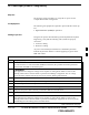
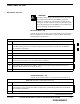
Frame Configuration DIP Switch – continued Expansion 1 Frame DIP Switch The switch settings must be verified and set before power is applied to the BTS. Refer to Figure 5-2 or Table 5-2 for the expansion 1 frame. Table 5-2: Frame ID Switch Position – Expansion 1 Frame 1 2 3 4 DN UP –– –– –– = Don’t Care. These switch positions do not affect the BTS. Expansion 2 Frame DIP Switch The switch settings must be verified and set before power is applied to the BTS.
Pre–Power Up Test (Indoor) Objective This procedure check for any electrical problems and verifies the operation and tolerances of the cell site BTS power supply prior to applying power for the first time.
Pre–Power Up Test (Indoor) – continued Table 5-5: BTS DC Pre–Power Test Step Action 3 At the rear of the BTS, verify that 20 or 25 A circuit breaker is OFF (pulled out). See Figure 5-3 or Figure 1-9. 4 Use a DMM (set to ohms) and verify the resistance on the –48V or +27V bus.
Pre–Power Up Test (Indoor) – continued Table 5-6: cCLPA DC Pre–Power Test 5 Step Action 1 Ensure that DC power is disengaged at the source. Verify that the DC power cable has been connected using the procedure in Table 4-8. 2 Remove I/O panel cover. 3 At the bottom of the cCLPA, verify that 20 A circuit breaker to OFF (pulled out). See Figure 5-4. 4 Us a DMM (set to ohms) and verify the resistance on the –48V or +27 V bus.
AC Power Input (Outdoor Configuration) Objective The objective of this procedure is to verify the AC power for the Compact BTS outdoor configuration.
AC Power Input (Outdoor Configuration) – continued Table 5-7: PDE Initial Power –Up Test Step Action 7 Using a DMM set toVAC, measure the voltage at the AC terminal block. DMM should indicate 200–240 VAC. Adjust AC voltage as necessary. 8 Remove DMM. 9 If there is nothing further to do, replace safety shield. Secure to cabinet with 2 nuts and washers. Use an adjustable wrench to tighten nuts. Torque nuts to 3.4 N–M (20 in–lbs).
Battery Backup DC Power Input (Outdoor Configuration) Objective The objective of this procedure is to verify the Battery Backup DC power for the Compact BTS outdoor configuration. Cable Descriptions and Part Numbers Table 5-8 gives the cable description and part number for the recommended cable. Consult manufacturer’s installation guide for further information. Table 5-8: Cable Descriptions and Part Numbers Cable Qty.
Battery Backup DC Power Input (Outdoor Configuration) – continued Table 5-9: Procedure to Verify Battery Backup DC Power Test Step Action 2 If not already done, connect Battery Backup DC power cable to batteries. 3 If not already done, remove safety shield covering DC terminal block. 4 Verify that Battery Backup DC power cable is securely connected to DC terminal block of PDE. 5 Verify that circuit breakers on PDE front panel are disengaged (pulled out or set to “O” (OFF)).
Initial Power–Up Test Initial Power–Up Tests WARNING Potentially lethal voltage and current levels are present in the Compact BTS. This test must NOT be performed without a second person present capable of administering emergency medical treatment. Remove all decorative metal before beginning this test. Do NOT wear a grounding strap when performing voltage measurements. BTS Initial Power–Up Perform the procedure in Table 5-10 to verify input power.
Initial Power–Up Test – continued Table 5-11: Procedure cCLPA Initial Power–Up Step Action 2 If not already done, remove cCLPA I/O panel cover. 3 Connect DC power to cCLPA I/O board DC terminal block. 4 Turn on DC power source. 5 Using a DMM (set to VDC), measure the voltage at the cCLPA I/O board terminal block. DC voltage should measure in the range of –60 to –40 VDC or +20 to +34 VDC. Adjust DC power source as necessary. 6 Remove DMM and install I/O panel cover.
Initial Power–Up Test – continued Table 5-12: TME DC Initial Power–Up Test Step Action 11 If not already done, connect PDA to BTS. (Three appropriately marked cables .) 12 Engage (push in) TME circuit breaker on PDA. NOTE Fans on HMS and BTS begin to operate. With TME cable connected the controller for the HMS and BTS is bypassed, and DC power is supplied as long as the TME circuit breaker is engaged. 13 Using a DMM set to VDC, measure the voltage at the BTS DC Input connector.
Remove Power Removing BTS Power Perform the procedure in Table 5-13, if power must be removed from the BTS. Table 5-13: Procedure to Remove Power to BTS Step Action 1 For indoor configuration, set the 20A or 25 A circuit breaker to OFF (pulled out). See Figure 5-3. For outdoor configuration, open TME and pull circuit breaker on PDA. Set TME circuit breaker on PDE to OFF. 2 Confirm all LEDs are OFF.
Chapter 6: Optimization and Calibration Table of Contents MAY 2004 Preliminary Operations: Overview . . . . . . . . . . . . . . . . . . . . . . . . . . . . . . . . . . . Introduction . . . . . . . . . . . . . . . . . . . . . . . . . . . . . . . . . . . . . . . . . . . . . . Cicruit Backhaul Operation . . . . . . . . . . . . . . . . . . . . . . . . . . . . . . . . . . Packet Backhaul Operation . . . . . . . . . . . . . . . . . . . . . . . . . . . . . . . . . . Cell–site Types . . . . . . . . . . . . . . .
Table of Contents 6 – continued Basic LMF Operation . . . . . . . . . . . . . . . . . . . . . . . . . . . . . . . . . . . . . . The LMF Display and the BTS . . . . . . . . . . . . . . . . . . . . . . . . . . . . . . . Graphical User Interface Overview . . . . . . . . . . . . . . . . . . . . . . . . . . . . Understanding GUI Operation . . . . . . . . . . . . . . . . . . . . . . . . . . . . . . . . Command Line Interface Overview . . . . . . . . . . . . . . . . . . . . . . . . . . . . Logging Into a BTS .
Table of Contents – continued Calibrate Test Cabling Using Signal Generator & Spectrum Analyzer . . . . . . . . . . . . . . . . . . . . . . . . . . . . . . . . . . . . . . . . . . . . . . . . . Setting Cable Loss Values . . . . . . . . . . . . . . . . . . . . . . . . . . . . . . . . . . . Setting TX and RX Directional Coupler Loss Value . . . . . . . . . . . . . . 6-71 6-73 6-74 Bay Level Offset Calibration . . . . . . . . . . . . . . . . . . . . . . . . . . . . . . . . . . . . . . .
Table of Contents – continued Notes 6 1X SC480 BTS Hardware Installation, Optimization/ATP, and FRU MAY 2004 PRELIMINARY
Preliminary Operations: Overview Introduction This section first verifies proper frame equipage against the site-specific documentation supplied for each BTS application. Cicruit Backhaul Operation If circuit backhaul operation is being used, perform the procedures described in this chapter. Refer to the LMF Help, if further information is needed. Packet Backhaul Operation If packet backhaul configuration is being used, perform the procedures described in Appendix I.
Preliminary Operations: Overview S Effective Rate Power (ERP) table for all TX channels to antennas respectively. Motorola System Engineering specifies the ERP of a transmit antenna based on the site geography, antenna placement, and government regulations. Working from this ERP requirement, the antenna gain, (dependent on the units of measurement specified) and antenna feed line loss can be combined to determine the required power of the BTS.
Ethernet LAN Ethernet LAN Termination For proper operation, the BTS Ethernet Local Area Network (LAN) connections must be terminated with a 50–ohm loads. This is done by placing four (4) 50–ohm BNC terminations on the LAN A and B external IN and OUT connectors located on the rear of the BTS. This is only done on stand–alone BTSs. The front panel LAN connections are not terminated with loads. Verify that the LAN A and B external IN and OUT connectors at the rear of the BTS have terminations installed.
Introduction to Optimization and Calibration Overview This section describes procedures for isolating the BTS from the span lines, preparing and using the WinLMF, downloading system operating software, CSA reference verification/optimization, set up and calibration of the supported test equipment, and transmit/receive paths are functioning properly. NOTE Before using the WinLMF, use an editor to view the “CAVEATS” section in the “readme.txt” file in the c:\wlmf folder for any applicable information.
Introduction to Optimization and Calibration – continued 10. If the TX calibration fails again, troubleshoot and correct the problem causing the failure, and repeat the full optimization for the failed path. 11. If the TX calibration and audit portion of the full optimization passes for a path but some of the TX or RX tests fail, troubleshoot and correct the problem causing the failure, and run the individual tests as required until all TX and RX tests have passed for all paths.
Introduction to Optimization and Calibration – continued NOTE Refer to Figure 6-2 and the WinLMF Help function on–line documentation for additional information on the layout of the WinLMF directory structure (including CDF/NECF file locations and formats). BTS System Software Download BTS system software must be successfully downloaded to the BTS processor boards before optimization can be performed. BTS operating code is loaded from the WinLMF computer terminal.
Preparing the LMF Overview of Packet BTS files R16.0 and earlier releases had the configuration file called CDF for each BTS and CBSC used by WinLMF. In 16.1 Packet BTS, BTS with GLI3 booting in packet binary, the CDF is replaced by two new configuration files called Network Element Configuration Base (NECB) and Network Element Change Journal (NECJ).
Preparing the LMF – continued WinLMF Features and Installation Requirements Before optimization can be performed, the WinLMF application software must be installed and configured on a computer platform meeting Motorola–specified requirements. NOTE For the WinLMF graphics to display properly, the computer platform must be configured to display more than 256 colors. See the operating system software instructions for verifying and configuring the display settings.
Preparing the LMF – continued FTP Server Port in use On some Windows 2000 installations, a process called “inetd.exe” makes the FTP server port 21 unusable by the WinLMF. If the WinLMF reports that the FTP server could not start because the port is in use, make sure the inetd.exe is not running by using the Task Manager’s process list. If inetd.exe is running, end the process by selecting it and clicking the “End Process” button. Inetd32.exe is NOT the same and ending it will not resolve this problem.
Preparing the LMF – continued :\ Where: = the WinLMF computer drive letter where the CDMA WinLMF home directory is located. = the directory path or name where the CDMA WinLMF is installed. NECF Filename Conventions and Directory Location NECF The NECF actually consists of two files: the NECB and NECJ. The naming convention for the NECB and NECJ is: NECB*bts#.xml NECJ*bts#.
Preparing the LMF – continued WinLMF Operating System Installation This section provides information and instructions for installing and updating the WinLMF software and files.
Preparing the LMF – continued Copy BTS CDF (or NECF) and CBSC CDF Files to the WinLMF Computer Before logging on to a BTS with the WinLMF computer to execute optimization/ATP procedures, the correct bts-#.cdf (or bts–#.necf) and cbsc-#.cdf files must be obtained from the CBSC and put in a bts-# folder in the WinLMF computer. This requires creating versions of the CBSC CDF files on a DOS–formatted floppy diskette and using the diskette to install the CDF files on the WinLMF computer.
Preparing the LMF – continued Table 6-3: Copying CDF or NECF Files to the WinLMF Computer n Step 4 Action Type mount and press the Enter key. NOTE S Look for the “floppy/no_name” message on the last line displayed. S If the eject command was previously entered, floppy/no_name will be appended with a number. Use the explicit floppy/no_name reference displayed when performing step 7. 5 Change to the directory, where the files to be copied reside, by typing cd (e.g.
Preparing the LMF – continued Creating a Named HyperTerminal Connection for MMI Communication Confirming or changing the configuration data of certain BTS Field Replaceable Units (FRU) requires establishing an MMI communication session between the WinLMF and the FRU. Using features of the Windows operating system, the connection properties for an MMI session can be saved on the WinLMF computer as a named Windows HyperTerminal connection.
Preparing the LMF – continued Table 6-4: Create HyperTerminal Connection Step 5 Action In the Port Settings tab of the COM# Properties window displayed, configure the RS–232 port settings as follows: S S S S S Bits per second: 9600 Data bits: 8 Parity: None Stop bits: 1 Flow control: None 6 Click OK. 7 Save the defined connection by selecting: File > Save 8 Close the HyperTerminal window by selecting: File > Exit 9 Click the Yes button to disconnect when prompted.
Span Lines – Interface and Isolation T1/E1 Span Interface NOTE At active sites, the OMC–R/CBSC must disable the BTS and place it out–of–service (OOS). DO NOT remove the span line cable connectors until the OMC–R/CBSC has disabled the BTS. Before connecting the WinLMF computer to the BTS LAN, the OMC–R/CBSC must disable the BTS and place it OOS. This will allow the WinLMF to control the BTS, and prevent the CBSC from inadvertently sending control information to the BTS during WinLMF–based tests.
LMF to BTS Connection Connect the WinLMF to the BTS The WinLMF computer may be connected to the LAN A or B connector located on the front panel or at the rear of the BTS. Figure 6-3 below shows the general location of these connectors. LAN A is considered the primary LAN. Table 6-6: Connecting the WinLMF to the BTS n Step 1 Action For indoor configuration, remove BTS front panel cover. For outdoor configuration, unlock and open TME right side door and remove BTS front panel cover.
Using the LMF Basic LMF Operation LMF Coverage in This Publication – The LMF application program supports maintenance of both CDMA and SAS BTSs. All references to the LMF in this publication are to the CDMA portion of the program.
Using the LMF – continued The LMF Display and the BTS BTS Display – When the LMF is logged into a BTS, a frame tab is displayed for each BTS frames. The frame tab will be labeled with “CDMA” and the BTS number, a dash, and the frame number (for example, BTS–812–1 for BTS 812, RFMF 1). If there is only one frame for the BTS, there will only be one tab.
Using the LMF – continued and NECB and NECJ files which point to a tape release stored on the GLI3. When the GLI3 has control of a card it will maintain that card with the code on that tape release. – Figure 6-7 depicts a packet mode site that has the MCC–1 and the BBX–1 cards under LMF control. Notice that the “X” is missing from the front of these two cards. For detailed information on performing these and other LMF operations, refer to the LMF Help function on–line documentation.
Using the LMF – continued Figure 6-5: Self–Managed Network Elements (NEs) State of a Packet Mode 6 MAY 2004 1X SC480 BTS Hardware Installation, Optimization/ATP, and FRU PRELIMINARY 6-21
Using the LMF – continued Figure 6-6: Available Packet Mode Commands 6 6-22 1X SC480 BTS Hardware Installation, Optimization/ATP, and FRU PRELIMINARY MAY 2004
Using the LMF – continued Figure 6-7: Packet Mode Site with MCC–1 and BBX–1 under LMF Control 6 MAY 2004 1X SC480 BTS Hardware Installation, Optimization/ATP, and FRU PRELIMINARY 6-23
Using the LMF – continued Command Line Interface Overview The LMF also provides Command Line Interface (CLI) capability. Activate the CLI by clicking on a shortcut icon on the desktop. The CLI can not be launched from the GUI, only from the desktop icon. Both the GUI and the CLI use a program known as the handler. Only one handler can be running at one time. The architectural design is such that the GUI must be started before the CLI if you want the GUI and CLI to use the same handler.
Using the LMF – continued Logging Into a BTS Logging into a BTS establishes a communication link between the BTS and the LMF. An LMF session can be logged into only one BTS at a time. Prerequisites Before attempting to log into a BTS, ensure the following have been completed: S The LMF is correctly installed on the LMF computer. S A bts-nnn folder with the correct CDF/NECF and CBSC files exists.
Using the LMF – continued Table 6-7: BTS GUI Login Procedure n Step Action 4 Click on the desired BTS number. 5 Click on the Network Login tab (if not already in the forefront). 6 Enter correct IP address (normally 128.0.0.2) for a field BTS, if not correctly displayed in the IP Address box. 7 Type in the correct IP Port number (normally 9216) if not correctly displayed in the IP Port box. 8 Click on Ping.
Using the LMF – continued BTS Login from the CLI Environment Follow the procedures in Table 6-8 to log into a BTS when using the CLI environment. NOTE If the CLI and GUI environments are to be used at the same time, the GUI must be started first and BTS login must be performed from the GUI. Refer to Table 6-7 to start the GUI environment and log into a BTS. Table 6-8: BTS CLI Login Procedure n Step 1 Action Double–click the WinLMF CLI desktop icon (if the LMF CLI environment is not already running).
Using the LMF – continued Logging Out Logging out of a BTS is accomplished differently for the GUI and CLI operating environments. NOTE The GUI and CLI environments use the same connection to a BTS. If a GUI and the CLI session are running for the same BTS at the same time, logging out of the BTS in either environment will log out of it for both. When either a login or logout is performed in the CLI window, there is no GUI indication that the login or logout has occurred.
Using the LMF – continued Logging Out of a BTS from the CLI Environment Follow the procedure in Table 6-10 to logout of a BTS when using the CLI environment. Table 6-10: BTS CLI Logout Procedure n Step Action NOTE If the BTS is also logged into from a GUI running at the same time and further work must be done with it in the GUI, proceed to Step 2. 1 Log out of a BTS by entering the following command: logout bts– A response similar to the following will be displayed: LMF> 13:24:51.
Using the LMF – continued Establishing an MMI Communication Session Equipment Connection – Figure 6-8 illustrates common equipment connections for the LMF computer. For specific connection locations on FRUs, refer to the illustration accompanying the procedures which require the MMI communication session. If the Motorola SLN2006A MMI Interface Kit is not available, an MMI cable can be made, refer to Appendix D for more information.
Using the LMF – continued Figure 6-8: LMF Computer Common MMI Connections – Motorola MMI Interface Kit, SLN2006A RESET Button To MMI Connector MMI Connector 8–PIN NULL MODEM BOARD (TRN9666A) 8–PIN TO 10–PIN RS–232 CABLE (P/N 30–09786R01) 6 LMF COMPUTER RS–232 CABLE COM1 OR COM2 DB9–TO–DB25 ADAPTER FW00687 MAY 2004 1X SC480 BTS Hardware Installation, Optimization/ATP, and FRU PRELIMINARY 6-31
Using the LMF – continued Figure 6-9: MMI Connection Detail – Fabricated MMI Cable RESET Button To MMI Connector MMI Connector 8–PIN LMF COMPUTER OR EQUIVALENT FABRICATED MMI CABLE (SEE MMI CABLE FABRICATION APPENDIX D) COM1 OR COM2 6 DB–9 CONNECTOR Online Help Task oriented online help is available in the LMF by clicking on Help in the window menu bar, and selecting LMF Help from the pull–down menu.
Pinging the Processors Pinging the BTS For proper operation, the integrity of the Ethernet LAN A and B links must be verified. Figure 6-10 represents a typical BTS Ethernet configuration. The drawing depicts cabling and termination for both the A and B LANs. Ping is a program that sends request data packets to hosts on a network, in this case GLI modules on the BTS LAN, to obtain a response from the “target” host specified by an IP address.
Pinging the Processors NOTE The Ethernet LAN A and B cables and/or terminations must be installed on each frame/enclosure external LAN connector before performing this test. All other processor board LAN connections are made through the backplanes. Table 6-12: Pinging the Processors Step Action 1 If this is a first–time communication with a newly–installed frame or a GLI card which has been replaced, perform the procedure in Table 11-3 and then return to step 2.
Pinging the Processors Table 6-12: Pinging the Processors Step Action 14 If ping was unsuccessful after restarting the LMF computer, press the GLI front panel reset pushbutton and perform steps 7 through 10 again. 15 After the BTS has been successfully pinged, be sure the 50Ω termination was replaced on the BTS LAN B IN connector at the rear of the BTS. Disconnect the LMF cable from the front LAN A connector, and connect it to front LAN B (right–hand connector).
Download the BTS Overview Before a BTS can operate, each equipped device must contain device initialization (ROM) code. ROM code is loaded in all devices during manufacture, factory repair, or, for software upgrades, from the CBSC using the DownLoad Manager (DLM). Device application (RAM) code and data must be downloaded to each equipped device by the user before the BTS can be made fully functional for the site where it is installed.
Download the BTS – continued RAM code can be downloaded to a device that is in any state. After the download is started, the device being loaded will change to OOS_ROM (blue). When the download is completed successfully, the device will change to OOS_RAM (yellow). When code is downloaded to a GLI, the LMF automatically also downloads data and then enables the GLI. When enabled, the GLI will change to INS_ACT (bright green). For non–GLI devices, data must be downloaded after RAM code is downloaded.
Download the BTS – continued Verify GLI ROM Code Loads Devices should not be loaded with a RAM code version which is not compatible with the ROM code with which they are loaded. Before downloading RAM code and data to the processor cards, follow the procedure in Table 6-13 to verify the GLI devices are loaded with the correct ROM code for the software release used by the Base Station System.
Download the BTS – continued Download RAM Code and Data to GLI Prerequisites S Prior to performing these procedures, ensure a code file exists for each of the devices to be loaded. S The LMF computer is connected to the BTS (refer to Table 6-6), and is logged in using the GUI environment (refer to Table 6-7). Procedure Follow the procedure in Table 6-14 to download the firmware application code for GLI. The download code action downloads data and also enables the GLI.
Download the BTS – continued NOTE CSA devices are RAM code–loaded at the factory. RAM code is downloaded to CSA only if a newer software version needs to be loaded. When downloading to multiple devices, the download may fail for some of the devices (a time–out occurs). These devices can be loaded individually after completing the multiple download. Follow the steps in Table 6-15 to download RAM code and data to non–GLI devices.
Download the BTS – continued Prerequisites S GLI is INS_ACT (bright green) S CSA is OOS_RAM (yellow) or INS_ACT (bright green) Follow the procedure in Table 6-16 to select a CSA Clock Source. Table 6-16: Select CSA Clock Source n Step Action 1 Select the CSA for which the clock source is to be selected. 2 Click on Device in the BTS menu bar, and select CSA > Select Clock Source... in the pull–down menu list. – A CSA clock reference source selection window will appear.
Download the BTS – continued Table 6-17: Enable CSA n Step Action NOTE – After CSA have been successfully enabled, be sure the STA/ALM LED is steady green (alternating green/red indicates the card is in an alarm state). 2 If more than an hour has passed without the CSA enabling, refer to the CSA System Time – GPS & HSO/MSO Verification section of this chapter (see Table 6-19, Figure 6-11, and Table 6-20) to determine the cause.
CSA System Time – GPS & HSO/MSO Verification Clock Synchronization and Alarm (CSA) Sub–system Description Overview The primary function of the CSA card is to maintain CDMA system time. A GPS receiver provides the primary timing reference for all CDMA BTS’s During normal operation, the CSA clocking outputs are phase locked to the GPS receiver timing reference. The CSA supports either an on–board GPS receiver module (RF GPS) or Remote GPS (RGPS) receiver.
CSA System Time – GPS & HSO/MSO Verification – continued High Stability Oscillator / Medium Stability Oscillator (HSO/MSO) General CSA and HSO/MSO The CSA utilizes timing signals provided by either an HSO or MSO to maintain BTS synchronization during the absence of valid GPS timing information. WHen a GPS timing signal is available the CSA is responsible for calibration of the HSO or MSO clock to maximize the backup timing interval.
CSA System Time – GPS & HSO/MSO Verification – continued CSA Frequency Verification The objective of this procedure is the initial verification of the Clock Synchronization Alarms (CSA) Module before performing the RF path verification tests. Test Equipment Setup (GPS & HSO/MSO Verification) Follow the steps outlined in Table 6-19 to set up test equipment.
CSA System Time – GPS & HSO/MSO Verification – continued Figure 6-11: CSA MMI Terminal Connection CSA card shown removed from frame SYNC MONITOR NULL MODEM BOARD (TRN9666A) FREQ. MONITOR 9–PIN TO 9–PIN RS–232 CABLE TO FRONT PANEL FW00372 LMF NOTEBOOK 6 DB9–TO–DB25 ADAPTER RS–232 SERIAL MODEM CABLE COM1 NOTES: 1.
CSA System Time – GPS & HSO/MSO Verification – continued Follow the steps outlined in Table 6-20 to initialize and verify proper GPS receiver functioning.
CSA System Time – GPS & HSO/MSO Verification – continued Table 6-20: GPS Initialization/Verification Step Action 2– Cont At the completion of the HSO warmup cycle, the HSO clcok output is enabled allowing califd clock pulses to be detected by the CSA. An integer value should then be displayed in the HSO “Last Phase” entry of the “sources” command as show below. If the HSO or MSO calibration cycle is not completed within 2 hours it will be necessary to inspect the HSO or MSO hardware.
CSA System Time – GPS & HSO/MSO Verification – continued Table 6-20: GPS Initialization/Verification Step 5 Action Enter the following command at the CSA> prompt to verify that the GPS receiver is in tracking mode. gstatus – Observe the following typical response: 27:27:11 CSA>gstatus 27:27:14 GPS Receiver Control Task State: tracking satellites. 27:27:14 Time since last valid fix: 0 seconds 27:27:14 Frame type (0): master 27:27:14 27:27:14 Recent Change Data: 27:27:14 GPS time offset 0 ns.
CSA System Time – GPS & HSO/MSO Verification – continued Table 6-20: GPS Initialization/Verification Step 7 Action If steps 1 through 6 pass, the GPS is good. NOTE If any of the above mentioned areas fail, verify that: – If Initial position accuracy is “estimated” (typical), at least 4 satellites must be tracked and visible (1 satellite must be tracked and visible if actual lat, log, and height data for this site has been entered into CDF file).
Test Equipment Setup Connecting Test Equipment to the BTS The following types of test equipment are required to perform calibration and ATP tests: S WinLMF S Communications system analyzer model supported by the WinLMF S Power meter model supported by the WinLMF (required when using the HP 8921A/600 and Advantest R3465 analyzers) S Non–radiating transmit line termination load S Directional coupler and in–line attenuator S RF cables and adapters Refer to Table 6-21 for an overview of connections for test
Test Equipment Setup – continued S CyberTest (High Power Configurations only) S Advantest R3267 spectrum analyzer with R3562 signal generator S Advantest R3465 spectrum analyzer with R3561L signal generator and HP–437B or Gigatronics Power Meter S Agilent E4406A transmitter test set with E4432B signal generator S Agilent 8935 series E6380A communications test set (formerly HP 8935) S Hewlett–Packard HP 8921 (with CDMA interface and, for 1.
Test Equipment Setup – continued Test Equipment Connection Charts To use the following charts to identify necessary test equipment connections, locate the communications system analyzer being used in the COMMUNICATIONS SYSTEM ANALYZER columns, and read down the column. Where a dot appears in the column, connect one end of the test cable to that connector. Follow the horizontal line to locate the end connection(s), reading up the column to identify the appropriate equipment and/or BTS connector.
Test Equipment Setup – continued CDMA2000 1X/IS–95A/B–capable Test Equipment Connections Table 6-22 depicts the interconnection requirements for currently available test equipment supporting both CDMA 2000 1X and IS–95A/B which meets Motorola standards and is supported by the WinLMF. Table 6-22: CDMA2000 1X/IS–95A/B Test Equipment Interconnection COMMUNICATIONS SYSTEM ANALYZER SIGNAL EVEN SECOND SYNCHRONIZATION 19.
Test Equipment Setup – continued Equipment Warm-up IMPORTANT * Warm-up BTS equipment for a minimum of 60 minutes prior to performing the BTS optimization procedure. This assures BTS stability and contributes to optimization accuracy. – Time spent running initial or normal power-up, hardware/firmware audit, and BTS download counts as warm-up time. WARNING Before installing any test equipment directly to any BTS TX OUT connector, verify there are no CDMA channels keyed.
Test Equipment Setup – continued Figure 6-12: IS–95A/B and CDMA 2000 1X Cable Calibration Test Setup – Agilent E4406A/E4432B and Advantest R3267/R3562 SUPPORTED TEST SETS CALIBRATION SET UP A. SHORT CABLE CAL Motorola CyberTest ÎÎÎ ÎÎÎÏ ANT IN SHORT CABLE TEST SET RF GEN OUT Note: The 30 dB directional coupler is not used with the Cybertest test set. The TX cable is connected directly to the Cybertest test set. B.
Test Equipment Setup – continued Figure 6-13: IS–95A/B and CDMA 2000 1X Cable Calibration Test Setup – Agilent E4406A/E4432B and Advantest R3267/R3562 SUPPORTED TEST SETS CALIBRATION SET UP A. SHORT CABLE CAL Agilent E4432B (Top) and E4406A (Bottom) SHORT CABLE RF OUTPUT 50 Ω TEST SET B. RX TEST SETUP N–N FEMALE ADAPTER RF INPUT 50 Ω RX CABLE SHORT CABLE NOTE: TEST SET 10 MHZ IN ON REAR OF SIGNAL GENERATOR IS CONNECTED TO 10 MHZ OUT (SWITCHED) ON REAR OF TRANSMITTER TESTER (FIGURE B-18).
Test Equipment Setup – continued Set-up for TX Calibration Figure 6-14 and Figure 6-15 show the test set connections for TX calibration. Figure 6-14: TX Calibration Test Setup – CyberTest (IS–95A/B) and Agilent 8935 (IS–95A/B and CDMA2000 1X) TEST SETS TRANSMIT (TX) SET UP POWER SENSOR Motorola CyberTest ÎÎÎ ÎÎÎ ÎÎÎÏ Communications System Analyzer 100–WATT (MIN.) NON–RADIATING RF LOAD NOTE: THE 30 DB DIRECTIONAL COUPLER IS NOT USED WITH THE CYBERTEST TEST SET.
Test Equipment Setup – continued Figure 6-15: TX Calibration Test Setup – Using Power Meter TEST SETS TRANSMIT (TX) SET UP NOTE: THE HP8921A AND ADVANTEST R3465 CANNOT BE USED FOR TX CALIBRATION. A POWER METER MUST BE USED. POWER SENSOR NOTE: TO PERFORM LOW POWER CALIBRATION THE 30 DB DIRECTIONAL COUPLER AND 0–20 DB ATTENUATOR ARE NOT REQUIRED. Power Meter 100–WATT (MIN.) NON–RADIATING RF LOAD TX TEST CABLE Hewlett Packard Model HP 8921A (for 800 MHz) DIRECTIONAL COUPLER (30 DB) 50 Ω TERM .
Test Equipment Setup – continued Figure 6-16: TX Calibration Test Setup – Agilent E4406A and Advantest R3567 (IS–95A/B and CDMA2000 1X) TEST SETS TRANSMIT (TX) SET UP Agilent E4406A POWER SENSOR NOTE: IF BTS IS EQUIPPED WITH DRDCS (DUPLEXED RX/TX SIGNALS), CONNECT THE TX TEST CABLE TO THE DRDC ANTENNA CONNECTOR. Communications SystemAanalyzer RF INPUT 50 Ω OR INPUT 50 Ω 100–WATT (MIN.
Test Equipment Setup – continued Set–up for ATP Figure 6-17 and Figure 6-18 show the test set connections for ATP tests. Figure 6-17: IS–95A/B ATP Test Set–up– CyberTest, Advantest R3465, and Agilent 8935 TEST SETS Optimization/ATP SET UP Motorola CyberTest SYNC MONITOR EVEN SEC TICK PULSE REFERENCE FROM CSA CARD FREQ MONITOR 19.6608 MHZ CLOCK REFERENCE FROM CSA CARD IMPORTANT: WHEN PERFORMING LOW POWER TESTING BYPASS THE COUPLER AND ATTENUATOR AND CONNECT DIRECTLY TO THE ANALYZER.
Test Equipment Setup – continued Figure 6-18: IS–95A/B ATP Test Setup – HP 8921A TEST SETS Optimization/ATP SET UP Hewlett Packard Model HP 8921A W/PCS Interface (for 1900 MHz) SYNC MONITOR EVEN SEC TICK PULSE REFERENCE FROM CSA CARD FREQ MONITOR 19.6608 MHZ CLOCK REFERENCE FROM CSA CARD RX TEST CABLE RF OUT ONLY PCS INTERFACE INPUT/OUTPUT PORTS Signal Generator HP PCS INTERFACE* RF IN/OUT GPIB CONNECTS TO BACK OF UNITS Communications System Analyzer 100–WATT (MIN.
Test Equipment Setup – continued Figure 6-19: IS–95A/B and CDMA2000 1X ATP Test Setup Agilent Test Equipment TEST SETS Optimization/ATP SET UP RF OUTPUT 50 Ω Agilent E4432B (Top) and 8935 Series E6380A (Bottom) RF OUTPUT 50 Ω RX TEST CABLE ÁÁ ÁÁ ÁÁ ÁÁ BNC “T” NOTES: 100–WATT (MIN.) NON–RADIATING RF LOAD 10 MHZ IN PATTERN TRIG IN GPIB Communications System Analyzer EXT REF IN TRIGGER IN OR EVEN SEC SYNCH IN 10 MHZ REF OUT OR 10 MHZ OUT HP–IB OR GPIB TX TEST CABLE FREQ MONITOR 19.
Test Equipment Setup – continued Figure 6-20: IS–95A/B and CDMA2000 1X Optimization/ATP Test Setup – Agilent E4432B/8935 Series E6380A and E4432B/E4406A Test Equipment TEST SETS Optimization/ATP SET UP RF OUT 50 Ω Advantest R3267 (Top) and R3562 (Bottom) Signal Generator MOD TIME BASE IN TO EXT TRIG ON REAR OF SPECTRUM ANALYZER EXT TRIG IN SYNTHE REF IN GPIB RX TEST CABLE 100–WATT (MIN.
Test Set Calibration Background Proper test equipment calibration helps to ensure accurate BTS optimization and acceptance testing by assuring that the test equipment and associated cables do not introduce measurement errors. NOTE If the test equipment set being used to optimize or test the BTS has been calibrated and maintained as a set, this procedure does not need to be performed. This procedure must be performed prior to beginning the optimization.
Test Set Calibration – continued Manual Agilent E4406A Transmitter Tester – The E4406A does not support the power level zeroing calibration performed by the WinLMF. If this instrument is to be used for Bay Level Offset calibration and calibration is attempted with the WinLMF Calibrate Test Equipment function, the WinLMF will return a status window failure message stating that zeroing power is not supported by the E4406A.
Test Set Calibration – continued Selecting Test Equipment Test equipment may be selected either manually with operator input or automatically using the WinLMF autodetect feature. Manually Selecting Test Equipment in a Serial Connection Tab Test equipment can be manually specified before or after the test equipment is connected. The WinLMF does not attempt to verify the test equipment is actually detected when manual selection is specified.
Test Set Calibration – continued Automatically Selecting Test Equipment in the Serial Connection Tab When using the auto-detection feature to select test equipment, the WinLMF determines which test equipment items are actually communicating with WinLMF. Follow the procedure in Table 6-24 to use the auto-detection feature. Table 6-24: Procedure for Selecting Test Equipment Using Auto-Detect Step Action 1 In the WinLMF window menu bar, click Tools and select Options... from the pull–down menu.
Test Set Calibration – continued Prerequisites S WinLMF computer serial port and test equipment are connected to the GPIB box. S Test equipment is turned on and has warmed up for at least 60 minutes. S Test equipment has been selected in the WinLMF (Table 6-23 or Table 6-24) Follow the procedure in Table 6-25 to calibrate the test equipment. Table 6-25: Procedure for Test Equipment Calibration Step Action 1 From the Util menu, select Calibrate Test Equipment from the pull–down menu.
Test Set Calibration – continued 3. Measure the loss of the short cable plus the TX test cable configuration. The TX test cable configuration normally consists of two coax cables with type–N connectors, a directional coupler, a termination load with sufficient rating to dissipate the BTS output power, and an additional attenuator, if required by the BTS type. The total path loss of the TX test configuration must be as required for the BTS (normally 30 or 50 dB).
Test Set Calibration – continued Table 6-26: Procedure to Test Cabling Calibration using Communication System Analyzer n Step Action Enter one or more channel numbers in the Channels box. 2 NOTE Multiple channel numbers must be separated by a comma with no spaces (for example: 200,800). When two or more channel numbers are entered, the cables will be calibrated for each channel. Interpolation will be accomplished for other channels, as required, for TX calibration.
Test Set Calibration – continued Figure 6-21: Cal Setup for TX/Duplexed RX Test Cabling Using Signal Generator & Spectrum Analyzer THIS WILL CONNECT TO THE BTS TX ANTENNA CONNECTOR DURING TX CALIBRATION AND TO THE TX/RX ANTENNA CONNECTORS DURING ATP TESTS. Signal Generator Spectrum Analyzer 40W NON–RADIATING RF LOAD A Signal Generator SHORT TEST CABLE 50 OHM TERMINATION Spectrum Analyzer 20DB 20 W IN–LINE ATTENUATOR FOR 1.
Test Set Calibration – continued Figure 6-22: Cal Setup for Non–Duplexed RX Test Cabling Using Signal Generator & Spectrum Analyzer Signal Generator Signal Generator Spectrum Analyzer CONNECTION TO THE COMMUNICATIONS SYSTEM ANALYZER RF OUTPUT CONNECTOR DURING RX MEASUREMENTS A SHORT TEST CABLE Spectrum Analyzer CONNECTION TO THE BTS RX ANTENNA CONNECTOR DURING RX ATP SHORT TEST CABLE BULLET CONNECTOR IMPORTANT: IF BTS TX/RX SIGNALS ARE DUPLEXED, THE RX TEST CABLE CONNECTS TO THE DUPLEXED ANTENNA C
Test Set Calibration – continued Table 6-29: Procedure for Setting Cable Loss Values Step Action 4 To edit existing values, click in the data box to be changed and change the value. 5 To delete a row, click on the row and then click on the Delete Row button. 6 For each tab with changes, click on the Save button to save displayed values. 7 Click on the Dismiss button to close the window. NOTE S Values entered or changed after the Save button was used will be lost when the window is dismissed.
Test Set Calibration – continued Table 6-30: Procedure for Setting TX and RX Directional Coupler Loss Values Step 6 Action Click on the Dismiss button to close the window. NOTE S Values entered or changed after the Save button is used will be lost when the window is dismissed. S The In–Service Calibration check box in the Tools > Options > BTS Options tab must be checked before entered TX coupler loss values will be used by the TX calibration and audit functions.
Bay Level Offset Calibration Purpose of Bay Level Offset Calibration Bay Level Offset (BLO) calibration is the central activity of the optimization process. BLO calibration compensates for normal equipment variations within the BTS RF paths and assures the correct transmit power is available at the BTS antenna connectors to meet site performance requirements. What is BLO Calibration? Description BLO calibration is the complete title of what is normally referred to as “calibration.
Bay Level Offset Calibration – continued BLO Calibration Data File During the calibration process, the LMF creates a calibration (CAL) data file where BLO values are stored. After calibration has been completed, these offset values must be downloaded to the BBXs using the LMF BLO download function. A detailed description of the file organization and content is provided in the following paragraphs NOTE Due to the size of the file, Motorola recommends printing out a copy of a bts–#.
Bay Level Offset Calibration – continued CAL File and BLO Data Download When BLO data is downloaded to the BBXs after calibration, the data is downloaded to the devices in the order it is stored in the CAL file. TX calibration data (entries C[1] – C[60]) are sent first. Data for the ten BBX slot 1 calibration points (entries C[1] – C[20]) are sent initially, followed by data for the ten BBX slot 2 calibration points (entries C[21] – C[40]), and so on.
Bay Level Offset Calibration – continued Transmit (TX) Path Calibration Description The assigned channel frequency and desired power level at the frame TX ports for transmit calibration are derived from the BTS CDF file. Each BBX at the site is assigned to a carrier. These are specified respectively in the carrier field of the ParentCARRIER parameter in each BBXs CDF file block.
Bay Level Offset Calibration – continued TX Calibration and the LMF The LMF Tests > TX > TX Calibration... and Tests > All Cal/Audit... selections perform TX BLO calibration testing for installed BBX(s). The All Cal/Audit... selection initiates a series of actions to perform TX calibration, and if calibration is successful, download BLO and perform TX audit. The TX Calibration... selection performs only TX calibration. When TX Calibration...
Bay Level Offset Calibration – continued S CDFPilot – This pattern setting is for advanced users. It performs calibration or audit using the CDF value for pilot gain and IS–97 gain values for all the other channels included in the Standard pattern setting (paging, synch, and six traffic). Using this pattern setting requires the selection of both a BBX and at least one MCC.
Bay Level Offset Calibration – continued Table 6-34: Procedure for Initial Set-up for TX Calibration n Step Action 1 Delete the existing calibration file (if any) from the BTS folder on LMF laptop from the location C:\wlmf\cdma\bts–#, where # is the BTS number. 2 To edit the nominal TX BLO, from the Util menu, select Edit > TX Nominal Offset.
Bay Level Offset Calibration – continued Prerequisites Before running this procedure, be sure that the following have been done: S The card in slot CSA, GLI, MCCs, and BBXs have correct code and data loads. S All BBXs are OOS_RAM (yellow). S If running calibration or audit using a test pattern other than Pilot, MCCs are INS_ACT (bright green). S Test equipment and test cables are calibrated and connected for TX calibration. S LMF is logged into the BTS in the GUI environment.
Bay Level Offset Calibration – continued Table 6-35: Procedure for All Cal/Audit and TX Calibration Step Action NOTE If necessary, the correct channel number may be manually entered into the Carrier # Channels box. 7 If at least one MCC was selected in Step 3, select the appropriate transfer rate (1 = 9600, 3 = 9600 1X) from the drop–down list in the Rate Set box. NOTE The rate selection of 3 is only available if 1X cards are selected for the test.
Bay Level Offset Calibration – continued Follow the steps in Table 6-36 to download the BLO data to the BBXs. Table 6-36: Procedure to Download BLO n Step Action 1 Select the BBX(s) to be downloaded. 2 Click Device in the BTS menu bar, and select Download > BLO from the pull–down menus. A status report window displays the result of the download. NOTE Selected device(s) do not change color when BLO is downloaded. 3 Click OK to close the status report window.
Bay Level Offset Calibration – continued Prerequisites Before running this test, the following should be done: S The CSA, GLIs, BBXs have correct code load. S The CSA and GLI are INS_ACT (bright green). S All BBXs are OOS_RAM (yellow). S Test equipment and test cables are calibrated and connected for TX BLO calibration. S LMF is logged into the BTS.
Bay Level Offset Calibration – continued Table 6-37: Procedure for BTS TX Path Audit n Step Action 8 From the Test Pattern pick list, select a test pattern. – Selecting Pilot (default) performs tests using a pilot signal only. – Selecting Standard performs tests using pilot, synch, paging and six traffic channels. This requires an MCC to be selected.
Bay Level Offset Calibration – continued S LMF is logged into the BTS S BBXs are OOS_RAM (yellow) S BLO has been downloaded to the BBXs Table 6-38: Create CAL File Step Action 1 Select the applicable BBXs. – The CAL file will be updated for the selected BBXs only. 2 Click on Device in the BTS menu bar, and select Create Cal File from the pull–down menu. – A status report window will appear and display the results of the action. 3 Click the OK button to close the status report window.
Chapter 7: Automated Acceptance Test Procedure (ATP) Table of Contents MAY 2004 Automated Acceptance Test Procedure – Introduction . . . . . . . . . . . . . . . . . . . . Introduction . . . . . . . . . . . . . . . . . . . . . . . . . . . . . . . . . . . . . . . . . . . . . . Reduced ATP . . . . . . . . . . . . . . . . . . . . . . . . . . . . . . . . . . . . . . . . . . . . . ATP Test Options . . . . . . . . . . . . . . . . . . . . . . . . . . . . . . . . . . . . . . . . . . ATP Prerequisites . . . . . . .
Table of Contents – continued Notes 7 1X SC480 BTS Hardware Installation, Optimization/ATP, and FRU PRELIMINARY MAY 2004
Automated Acceptance Test Procedure – Introduction Introduction General The Acceptance Test Procedures (ATP) allow Cellular Field Engineers (CFEs) to run automated acceptance tests on all BTS subsystem devices equipped in the CDF using the LMF and the test equipment it supports. Test Reports The CFE can choose to save the results of ATP tests to a report file from which ATP reports are generated for later printing. See the Generating an ATP Report section in this chapter.
Automated Acceptance Test Procedure – Introduction – continued 2. Retrieve Calibration Data required for normal site operation. In the unlikely event that the BTS passes these tests but has a forward link problem during normal operation, the CFE should then perform the additional TX tests for troubleshooting: TX spectral mask, TX rho, and TX code domain.
Automated Acceptance Test Procedure – Introduction – continued WARNING 1. All transmit connectors must be properly terminated for all ATP tests. 2. Before the FER is run, be sure that one of the following is done: – All transmitter connectors are properly terminated OR – The Compact PA is turned OFF (circuit breakers pulled) Failure to observe these warnings may result in bodily injury or equipment damage. EV–DO Optimization and ATP Appendix A contains procedures for testing the DO card using the LMF.
Acceptance Tests – Test Set Up Required Test Equipment The following test equipment is required: S S S S LMF Power meter (used with HP438 and Agilent 8935) Communications system analyzer Signal generator for FER testing (required for all communications system analyzers for 1X FER) WARNING Before installing any test equipment directly to any BTS TX OUT connector, verify that there are no CDMA channels keyed. At active sites, have the OMCR/CBSC place the carrier assigned to the cCLPAs under test OOS.
Abbreviated (All–inclusive) Acceptance Tests All–inclusive Tests General – The all–inclusive acceptance tests are performed from the LMF GUI environment. These all–inclusive tests are called abbreviated ATPs because they execute various combinations of individual acceptance tests with a single command. This allows verification of multiple aspects of BTS performance while minimizing time needed for individual test set up and initiation.
Abbreviated (All–inclusive) Acceptance Tests – continued All TX/RX ATP Test Follow the procedures in Table 7-2 to perform the abbreviated, all–inclusive transmit and receive test. Table 7-2: All TX/RX ATP Test Procedure Step 1 Action Set up the test equipment initially for abbreviated tests as described in Table 7-1.
Abbreviated (All–inclusive) Acceptance Tests – continued Table 7-2: All TX/RX ATP Test Procedure Step 11 Action Click the Save Results or Dismiss button. NOTE If Dismiss is used, the test results will not be saved in the test report file. All TX ATP Test Follow the procedures in Table 7-3 to perform the abbreviated, all–inclusive transmit test. Table 7-3: All TX ATP Test Procedure Step Action 1 Set up the test equipment for abbreviated tests per Table 7-1. 2 Select the BBXs and MCCs to be tested.
Abbreviated (All–inclusive) Acceptance Tests – continued Table 7-4: All RX ATP Test Procedure Step 1 Action Set up the test equipment for abbreviated tests per Table 7-1. * IMPORTANT If the LMF has been logged into the BTS with a different Multi–Channel Preselector setting than the one to be used for this test, the LMF must be logged out of the BTS and logged in again with the new Multi–Channel Preselector setting. Using the wrong MPC setting can cause a false test failure.
Individual Acceptance Tests–Introduction Individual Acceptance Tests The following individual ATP tests can be used to evaluate specific aspects of BTS operation against individual performance requirements. All testing is performed using the LMF GUI environment. TX Testing TX tests verify any given transmit antenna path and output power control. All tests are performed using the external, calibrated test equipment. All measurements are made at the appropriate BTS TX OUT connector(s).
Individual Acceptance Tests–Introduction – continued BTS FER This test verifies the BTS receive FER on all traffic channel elements currently configured on all equipped MCCs (fullrate at one percent FER) at an RF input level of –119 dBm on the main RX antenna paths using operator–selected, CDF–equipped MCCs and BBXs at the site. Diversity RX antenna paths are also tested using the lowest equipped MCC channel element ONLY.
TX Spectral Purity Transmit Mask Acceptance Test Background Overview – This test verifies the spectral purity of each operator–selected BBX carrier keyed up at a specific frequency specified in the current CDF. All tests are performed using the external, calibrated test equipment controlled by the same command. All measurements are made at the appropriate BTS TX antenna connector. Test Patterns – There are four operator–selectable test patterns with which this acceptance test can be performed.
TX Spectral Purity Transmit Mask Acceptance Test – continued Table 7-5: Test Spectral Purity Transmit Mask Step Action 2 Select the BBXs to be tested. 3 Click on Tests in the BTS menu bar, and select TX > TX Mask... from the pull–down menus. 4 Select the appropriate carrier(s) and sector(s) (carrier-bts#-sector#-carrier#) from those displayed in the Channels/Carrier pick list.
TX Spectral Purity Transmit Mask Acceptance Test – continued Figure 7-1: TX Mask Verification Spectrum Analyzer Display Mean CDMA Bandwidth Power Reference .
TX Waveform Quality (Rho) Acceptance Test Background Overview – This test verifies the transmitted pilot channel element digital waveform quality of each operator–selected BBX carrier keyed up at a specific frequency specified in the current CDF. All tests are performed using the external, calibrated test equipment controlled by the same command. All measurements are made at the appropriate TX antenna connector.
TX Waveform Quality (rho) Acceptance Test – continued Table 7-6: Test Waveform Quality (Rho) Step 8 Action Click the Save Results or Dismiss button. NOTE If Dismiss is used, the test results will not be saved in the test report file.
TX Pilot Time Offset Acceptance Test Background Overview – This test verifies the transmitted pilot channel element Pilot Time Offset of each operator–selected BBX carrier keyed up at a specific frequency specified in the current CDF. All tests will be performed using the external, calibrated test equipment controlled by the same command. All measurements will be made at the BTS TX antenna connector.
TX Pilot Time Offset Acceptance Test – continued Table 7-7: Test Pilot Time Offset Step 5 Action Verify that the correct channel number for the selected carrier is shown in the Carrier # Channels box. – If it is not, obtain the latest bts–#.cdf and cbsc–#.cdf files from the CBSC. NOTE If necessary, the correct channel number may be manually entered into the Carrier # Channels box. 6 Click OK to display a status bar followed by a Directions pop-up window.
TX Code Domain Power/Noise Floor Acceptance Test Background Overview – This test verifies the Code Domain Power and Noise Floor of each operator–selected BBX carrier keyed at a specific frequency specified in the current CDF. All tests are performed using the external, calibrated test equipment controlled by the same command. All measurements are made at the appropriate BTS TX antenna connector.
TX Code Domain Power/Noise Floor Acceptance Test – continued Table 7-8: Test Code Domain Power/Noise Floor Step Action 1 Set up the test equipment for TX acceptance tests per Table 7-1. 2 Select the BBXs and MCCs to be tested. 3 Click on Tests in the BTS menu bar, and select TX > Code Domain Power... from the pull–down menus. Select the appropriate carrier(s) and sector(s) (carrier-bts#-sector#-carrier#) from those displayed in the Channels/Carrier pick list.
TX Code Domain Power/Noise Floor Acceptance Test – continued Figure 7-2: Code Domain Analyzer CD Power/Noise Floor Display Examples Pilot Channel PILOT LEVEL MAX OCNS CHANNEL 8.2 dB 12.2 dB MAX OCNS SPEC. Active channels MIN OCNS SPEC. MIN OCNS CHANNEL MAX NOISE FLOOR MAXIMUM NOISE FLOOR: < –27 dB FOR IS–95A/B AND CDMA2000 1X Inactive channels Walsh 0 1 2 3 4 5 6 7 ... 64 Code Domain Power/Noise Floor (OCNS Pass) Example Pilot Channel PILOT LEVEL FAILURE – EXCEEDS MAX OCNS SPEC. 8.2 dB 12.
RX FER Acceptance Test Background Overview – This test verifies the BTS Frame Erasure Rate (FER) on all TCHs currently configured on operator–selected MCCs (fullrate at 1% FER) at –119 dBm. All tests are performed using the external, calibrated test equipment as the signal source controlled by the same command. Measurements are made at the specified BTS RX antenna connection.
RX FER Acceptance Test – continued Table 7-9: Test FER Step Action 7 Verify that the correct channel number for the selected carrier is shown in the Carrier # Channels box. – If it is not, obtain the latest bts–#.cdf and cbsc–#.cdf files from the CBSC. 8 NOTE If necessary, the correct channel number may be manually entered into the Carrier # Channels box. 9 * IMPORTANT If a companion frame with the inter–frame diversity RX cabling disconnected is being tested do not select BOTH in this step.
Generating an ATP Report Background Each time an ATP test is run, ATP data is updated and must be saved to an ATP report file using the Save Results button to close the status report window. The ATP report file will not be updated if the status reports window is closed using the Dismiss button.
Generating an ATP Report – continued Notes 7 7-24 1X SC480 BTS Hardware Installation, Optimization/ATP, and FRU PRELIMINARY MAY 2004
Chapter 8: Leave the Site Table of Contents Updating Calibration Data Files . . . . . . . . . . . . . . . . . . . . . . . . . . . . . . . . . . . . . Software Release caveats . . . . . . . . . . . . . . . . . . . . . . . . . . . . . . . . . . . . Copy and Load Cal File to to CBSC . . . . . . . . . . . . . . . . . . . . . . . . . . . 8-1 8-1 8-1 Prepare to Leave the Site . . . . . . . . . . . . . . . . . . . . . . . . . . . . . . . . . . . . . . . . . . External Test Equipment Removal . . . . . . . . . .
Table of Contents – continued Notes 8 1X SC480 BTS Hardware Installation, Optimization/ATP, and FRU PRELIMINARY MAY 2004
Updating Calibration Data Files Software Release caveats With Software Release 2.16.1.x, the packet BTS will NOT detect a new calibration file on the OMC–R. A manual workaround is available in bulletin cdma_g_bts_059. This will be corrected in Software Release 2.16.3. Software Release 2.16.3 will allow the user to load the calibration file from the LMF directly onto the MGLI.
Updating Calibration Data Files – continued Copying CAL Files from Diskette to the CBSC Follow the procedures in Table 8-2 to copy CAL files from a diskette to the CBSC. Table 8-2: Copying CAL Files from Diskette to the CBSC Step Action 1 Log into the CBSC on the OMC–R Unix workstation using your account name and password. 2 Place the diskette containing calibration files (cal files) in the workstation diskette drive. 3 Type in eject –q and press the Enter key.
Prepare to Leave the Site External Test Equipment Removal Perform the procedure in Table 8-3 to disconnect the test equipment and configure the BTS for active service. Table 8-3: Remove External Test Equipment Step 1 Action n WARNING Be sure no BBXs are keyed before performing this step. Failure to do so can result in personal injury and damage to BTS LPAs. Disconnect all external test equipment from all TX and RX connectors at the rear of the frame.
Prepare to Leave the Site – continued Table 8-4: Bring Modules into Service Step Action 4 Click Cancel to close the transceiver parameters window, if applicable. 5 Click OK to close the status report window. – The color of devices which successfully change to INS will change bright green. WinLMF Removal Perform the procedure in Table 8-5 as required to terminate the WinLMF GUI session and remove the WinLMF computer.
Prepare to Leave the Site – continued Final Checks before leaving site Be sure all requirements listed in Table 8-7 are completed before leaving the site. Table 8-7: Check Before Leaving the Site Step Action 1 When backup batteries are installed, all battery circuit breakers are ON (pushed in). 2 BTS circuit breaker is ON (pushed in). 3 No alarm conditions are being reported to the OMC–R.
Prepare to Leave the Site – continued Notes 8 8-6 1X SC480 BTS Hardware Installation, Optimization/ATP, and FRU PRELIMINARY MAY 2004
Chapter 9: Field Replaceable Unit Table of Contents MAY 2004 Introduction . . . . . . . . . . . . . . . . . . . . . . . . . . . . . . . . . . . . . . . . . . . . . . . . . . . . . Scope . . . . . . . . . . . . . . . . . . . . . . . . . . . . . . . . . . . . . . . . . . . . . . . . . . . Section Organization . . . . . . . . . . . . . . . . . . . . . . . . . . . . . . . . . . . . . . . 9-1 9-1 9-1 Fan Module . . . . . . . . . . . . . . . . . . . . . . . . . . . . . . . . . . . . . . . . . . . . . . . . .
Table of Contents 9 – continued System Impact/Considerations . . . . . . . . . . . . . . . . . . . . . . . . . . . . . . . Required Items . . . . . . . . . . . . . . . . . . . . . . . . . . . . . . . . . . . . . . . . . . . . Prerequisite . . . . . . . . . . . . . . . . . . . . . . . . . . . . . . . . . . . . . . . . . . . . . . Replacement Procedure . . . . . . . . . . . . . . . . . . . . . . . . . . . . . . . . . . . . . 9-21 9-21 9-21 9-21 Group Line Interface Card . . . . . . . . . . . . . . . . .
Table of Contents MAY 2004 – continued Prerequisite . . . . . . . . . . . . . . . . . . . . . . . . . . . . . . . . . . . . . . . . . . . . . . Replacement Procedure . . . . . . . . . . . . . . . . . . . . . . . . . . . . . . . . . . . . . 9-46 9-46 SDCX Module . . . . . . . . . . . . . . . . . . . . . . . . . . . . . . . . . . . . . . . . . . . . . . . . . . Introduction . . . . . . . . . . . . . . . . . . . . . . . . . . . . . . . . . . . . . . . . . . . . . . System Impact/Considerations . . . . . .
Table of Contents – continued System Impact/Considerations . . . . . . . . . . . . . . . . . . . . . . . . . . . . . . . Required Items . . . . . . . . . . . . . . . . . . . . . . . . . . . . . . . . . . . . . . . . . . . . Prerequisite . . . . . . . . . . . . . . . . . . . . . . . . . . . . . . . . . . . . . . . . . . . . . . Replacement Procedure . . . . . . . . . . . . . . . . . . . . . . . . . . . . . . . . . . . . . 9-83 9-83 9-83 9-83 Power Distribution Enclosure . . . . . . . . . . . . . . . . .
Introduction Scope The objective of the Field Replaceable Unit (FRU ) section contains OMC–R procedures and information and procedures for disassembling and/or replacing cards, modules, and components of the Compact BTS. The Compact BTS is a single cage, non–redundant configuration.
Introduction – continued Figure 9-1: Compact BTS Front Panel Layout without Front Panel Cover NOTE: Front cover panel is not shown.
Introduction – continued Figure 9-2: Compact BTS Fan and CCP2 Shelf Layout MCC LED GLI CSA ACTIVE PWR/ALM PWR/ALM PWR/ALM BPR A 19MHz ACTIVE NOTE: 1.
Fan Module Introduction The fan module is located above the CCP2 Shelf at the front of the Compact BTS. The fan mdoule is a modular device allowing easy replacement. The electrical connection for DC power is made through a connector at the rear of the module. The connector is automatically engaged when the fan module is inserted and seated. System Impact/Considerations NOTE At room temperature, the fan module is very quiet.
Fan Module – continued Upon completion of the replacement procedure, have the OMC–R operator verify that old alarms are cleared and that no new ones are reported. Replacement Procedure CAUTION This procedure requires working around circuitry that is extremely sensitive to Electrostatic Discharge (ESD). Wear a conductive, high impedance wrist strap during the procedure. Use appropriate safety measures.
Fan Module – continued Install Fan Module Use the procedure in Table 9-2 to install the fan module. Table 9-2: Procedure to Install Fan Module Step Action 1 Put on the ESD wrist strap or another approved grounding device. 2 Using both hands, set the fan module in the guide channels, and slide module in. 3 Ensure that fan module seats and front latch engages. 4 Notify operator that the fan replacement procedure is completed.
High and Medium Stability Oscillator Module Introduction The High Stability and Medium Stability Oscillator module provide a backup reference source in the case of Global Positioning System (GPS) failure. The HSO is capable of providing up to 24 hours, the synchronization initially established by the GPS reference signal. The MSO is capable of providing up to 8 hours. There is only one HSO or MSO equipped in the Compact BTS. The module is located in front, behind a cover, underneath the CCP2 Shelf.
High and Medium Stability Oscillator Module – continued Replacement Procedure CAUTION This procedure requires working around circuitry that is extremely sensitive to Electrostatic Discharge (ESD). Wear a conductive, high impedance wrist strap during the procedure. Use appropriate safety measures. If desired, record the BTS and HSO/MSO serial number of the failed unit in Table 9-54 at the end of this chapter. Remove HSO or MSO Module Follow the procedure in Table 9-3 to remove the HSO or MSO module.