
User's Manual

PN Offset Programming Information
68P64115A18–1
Mar 2003
1X SC 4812T Lite BTS Optimization/ATP Software Release R2.16.1.x
DRAFT
B-2
PN Offset Programming Information
PN Offset Background
All channel elements transmitted from a BTS in a particular 1.25 MHz
CDMA channel are orthonogonally spread by 1 of 64 possible Walsh
code functions; additionally, they are also spread by a quadrature pair of
PN sequences unique to each sector.
Overall, the mobile uses this to differentiate multiple signals transmitted
from the same BTS (and surrounding BTS) sectors, and to synchronize
to the next strongest sector.
The PN offset per sector is stored on the BBXs, where the
corresponding I & Q registers reside.
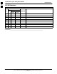
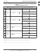
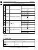
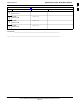
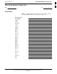
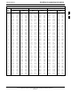
The PN offset values are determined by BTS sector (antenna) based on
the applicale CDF data field content. A breakdown of this information is
found in Table B-1.
PN Offset Usage
There are three basic RF chip delays currently in use. It is important to
determine what RF chip delay is valid to be able to test the BTS
functionality. This can be done by ascertaining if the CDF
FineTxAdj
value was set to “on” when the MCC was downloaded with “image
data”. The
FineTxAdj value is used to compensate for the processing
delay (approximately 20 mS) in the BTS using any type of mobile
meeting IS–97 specifications.
Observe the following guidelines:
S If the FineTxAdj value in the CDF is 101 (65 HEX), the FineTxAdj
has not been set. The I and Q values from the 0 table MUST be used.
If the
FineTxAdj value in the cdf file is 213 (D5 HEX), FineTxAdj has
been set for the 14 chip table.
S If the FineTxAdj value in the CDF file is 197 (C5 HEX), FineTxAdj
has been set for the 13 chip table.
NOTE
CDF file I and Q values can be represented in DECIMAL or
HEX. If using HEX, add 0x before the HEX value. If necessary,
convert HEX values in Table B-1 to decimal before comparing
them to cdf file I & Q value assignments.
– If a Qualcomm mobile is used, select I and Q values from the 13
chip delay table.
– If a mobile is used that does not have the 1 chip offset problem,
(any mobile meeting the IS–97 specification), select from the 14
chip delay table.
NOTE
If the wrong I and Q values are used with the wrong FineTxAdj
parameter, system timing problems will occur. This will cause
the energy transmitted to be “smeared” over several Walsh codes
(instead of the single Walsh code that it was assigned to),
causing erratic operation. Evidence of smearing is usually
identified by Walsh channels not at correct levels or present
when not selected in the Code Domain Power Test.
B