
User's Manual

Module Front Panel LED Indicators and Connectors68P64115A18–1
Mar 2003
1X SC 4812T Lite BTS Optimization/ATP Software Release R2.16.1.x
DRAFT
6-29
CSM LED Status Combinations
PWR/ALM LED
The CSMs include on-board alarm detection. Hardware and
software/firmware alarms are indicated via the front panel indicators.
After the memory tests, the CSM loads OOS–RAM code from the Flash
EPROM, if available. If not available, the OOS–ROM code is loaded
from the Flash EPROM.
S Solid GREEN – module is INS_ACT or INS_SBY no alarm.
S Solid RED – Initial power up or module is operating in a fault (alarm)
condition.
S Slowly Flashing GREEN – OOS_ROM no alarm.
S Long RED/Short GREEN – OOS_ROM alarm.
S Rapidly Flashing GREEN – OOS_RAM no alarm or
INS_ACT in DUMB mode.
S Short RED/Short GREEN – OOS_RAM alarm.
S Long GREEN/Short RED – INS_ACT or INS_SBY alarm.
S Off – no DC power or on-board fuse is open.
S Solid YELLOW – After a reset, the CSMs begin to boot. During
SRAM test and Flash EPROM code check, the LED is yellow. (If
SRAM or Flash EPROM fail, the LED changes to a solid RED and
the CSM attempts to reboot.)
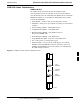
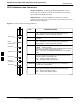
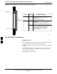
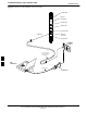
Figure 6-2: CSM Front Panel Indicators & Monitor Ports
PWR/ALM
Indicator
FREQ
MONITOR
SYNC
MONITOR
FW00303
6