
User's Manual

Power Delta Calibration
68P64115A18–1
Mar 2003
1X SC 4812T Lite BTS Optimization/ATP Software Release R2.16.1.x
DRAFT
H-12
HP8921A Power Delta Calibration
Use the HP8921A communications test set to measure power during ISC
only for IS–95A and B operation of 800 MHz systems. After the offset
value has been calculated, add it to the TX cable loss value.
Follow the procedure in Table H-4 to perform the HP8921A Power Delta
Calibration procedure.
NOTE
This procedure requires two HP8921A communication test sets.
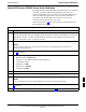
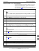
Table H-4: HP8921A Power Delta Calibration Procedure
Step Action
NOTE
Perform this procedure after test equipment has been allowed to warm–up and stabilize for a minimum
of 60 minutes. After it is warmed up and stabilized, calibrate the test equipment as described in the
“Test Set Calibration” section of Chapter NO TAG.
1
Zero the Power Meter prior to connecting the power sensor to the RF cable from the signal generator.
NOTE
For best accuracy, always re–zero the power meter before connecting the power sensor to the
component being calibrated.
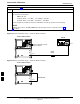
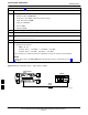
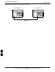
2 Connect a short RF cable between the HP8921A Duplex Out port and the HP437 power sensor (see
Figure H-8).
3 Set the HP8921A signal source as follows:
– Measure mode to CDMA Generator
– Frequency to the CDMA Calibration target frequency
– CW RF Path to IQ
– Output Port to Dupl
– Data Source to Random
– Amplitude to 0 dBm
4 Measure and record the power value reading on the HP437 Power Meter.
5 Record the Power Meter reading as result A ________________________.
6 Turn off the source HP8921A signal output, and disconnect the HP437.
NOTE
Leave the settings on the source HP8921A for convenience in the following steps.
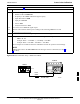
7 Connect the short RF cable between the source HP8921A Duplex Out port and the measuring
HP8921A RF–IN port (see Figure H-9).
8 Ensure that the source HP8921A settings are the same as in Step 3.
. . . continued on next page
H