
User's Manual

Test Equipment Inter–unit Connection, Testing, and Control
68P64115A18–1
Mar 2003
1X SC 4812T Lite BTS Optimization/ATP Software Release R2.16.1.x
DRAFT
F-14
Test Equipment Inter–unit Connection, Testing, and Control
Inter–unit Connection, Testing, and Control Settings
The following illustrations, tables, and procedures provide the
information necessary to prepare various items of CDMA test equipment
supported by the LMF for BTS calibration and/or acceptance testing.
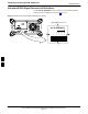
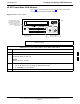
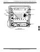
HP 8921A with PCS Interface Test Equipment Connections
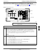
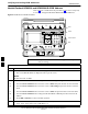
The following diagram depicts the rear panels of the HP 8921A test
equipment as configured to perform automatic tests. All test equipment
is controlled by the LMF via an IEEE–488/GPIB bus. The LMF expects
each piece of test equipment to have a factory-set GPIB address (refer to
Table F-5 and Figure F-6). If there is a communications problem
between the LMF and any piece of test equipment, verify that the GPIB
addresses have been set correctly and that the GPIB cables are firmly
connected to the test equipment.
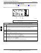
Figure F-11 shows the connections when not using an external 10 MHz
Rubidium reference.
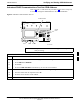
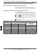
Table F-10: HP 8921A/600 Communications Test Set Rear Panel Connections Without Rubidium Reference
From Test Set: To Interface:
Connector Type
8921A 83203B CDMA 83236A PCS
C
onnector
T
ype
CW RF OUT CW RF IN SMC–female – SMC–female
114.3 MHZ IF OUT 114.3 MHZ IF IN SMC–female – SMC–female
IQ RF IN IQ RF OUT SMC–female – SMC–female
DET OUT AUX DSP IN SMC–female – SMC–female
CONTROL I/O CONTROL I/O 45–pin custom BUS
10 MHZ OUT SYNTH REF IN BNC–male – BNC–male
HPIB INTERFACE HPIB INTERFACE HPIB cable
10 MHZ OUT REF IN BNC–male – BNC–male
F