Technical Information 1X SC 4812T-MC BTS Hardware Installation Software Release R2.16.1.
SPECIFICATIONS SUBJECT TO CHANGE WITHOUT NOTICE Notice While reasonable efforts have been made to assure the accuracy of this document, Motorola, Inc. assumes no liability resulting from any inaccuracies or omissions in this document, or from use of the information obtained herein. The information in this document has been carefully checked and is believed to be entirely reliable. However, no responsibility is assumed for inaccuracies or omissions. Motorola, Inc.
SPECIFICATIONS SUBJECT TO CHANGE WITHOUT NOTICE Trademarks and Motorola are registered trademarks of Motorola, Inc. Product and service names profiled herein are trademarks of Motorola, Inc. Other manufacturers’ products or services profiled herein may be referred to by trademarks of their respective companies. Copyright 2003 Motorola, Inc.
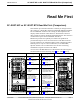
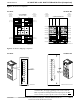
SC 4812T-MC vs SC 4812T BTS Read Me First (Comparison) 68P64115A19–4 Read Me First SC 4812T-MC vs SC 4812T BTS Read Me First (Comparison) This Read-me-first document describes a summary of changes between the existing SCt4812T BTS and the SC 4812T-MC (Multicarrier) BTS. The SC 4812T-MC is based on the existing SC 4812T platform and employs similar hardware and architecture. The differences between these products are briefly described and illustrated below.
SC 4812T-MC vs SC 4812T BTS Read Me First (Comparison) 68P64115A19–4 Figure 1: DC Power Input Connector Comparison SC 4812T SC 4812T–MC CABLE LUG COVER (1509789V01) DC CABLE (–) (+) DC CABLE GROMMET (0509591Y02) DC CONTACT DC CONTACT DC Connector Housing M10 NUT (0210971A09) M10 LOCK WASHER (0410985A02) (–) Input Connector/ DC Filter M10 FLAT WASHER (0410983B28) CRIMP LUG POWER INPUT STUD (+) FEED COVER (DO NOT REMOVE) ENCLOSURE BASE ti-CDMA-WP-00024-v01-ildoc-ftw ti-CDMA-WP-00074-v01-ildo
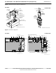
SC 4812T-MC vs SC 4812T BTS Read Me First (Comparison) 68P64115A19–4 Figure 3: PA Location Comparison SC 4812T SC 4812T–MC Sector Numbering 3 Sector (6 Sector) Sector Numbering 3 Sector (6 Sector) 2 to 1 Combiner 3 Sector or 6 Sector LPA 2B LPA 1B 3 Sector and 6 Sector C2, S1–3 (C2, S1–3) LPA 2C LPA 1C LPA 2D LPA 1D 1 2 4 5 CLPA 4A C2 (C2) CLPA 3B S3 C2 (C2) LPA 4B C4, S1–3 (C2, S4–6) LPA 4C S1 CLPA 1C C1 (C1) LPA 4A LPA 3C CLPA 2B CLPA 3A C1 (C1) C3 (C1) S2 C4 (C2) LPA
SC 4812T-MC vs SC 4812T BTS Read Me First (Comparison) 68P64115A19–4 Notes RMF-4 1X SC 4812T-MC BTS Hardware Installation - Software Release R2.16.1.
Table of Contents . . . Mar 2003 1X SC 4812T-MC BTS Hardware Installation - Software Release R2.16.1.
Table of Contents 68P64115A19–4 SC 4812T-MC vs SC 4812T BTS Read Me First (Comparison) . . . . . . . . . . . . . . . . . . . . . . . . . . . . . . . . . . . . RMF-2 Contents FCC Requirements . . . . . . . . . . . . . . . . . . . . . . . . . . . . . . . . . . . . . . . . . . . . . . . . . . . . . . . . . . . . . . . . . . . . . . . . . . Content . . . . . . . . . . . . . . . . . . . . . . . . . . . . . . . . . . . . . . . . . . . . . . . . . . . . . . . . . . . . . . . . . . . . . . . . . . . . .
Table of Contents 68P64115A19–4 Cable Labels . . . . . . . . . . . . . . . . . . . . . . . . . . . . . . . . . . . . . . . . . . . . . . . . . . . . . . . . . . . . . . . . . . . . . . . . Equipment Needed . . . . . . . . . . . . . . . . . . . . . . . . . . . . . . . . . . . . . . . . . . . . . . . . . . . . . . . . . . . . . . . . . . . Cabling Diagram . . . . . . . . . . . . . . . . . . . . . . . . . . . . . . . . . . . . . . . . . . . . . . . . . . . . . . . . . . . . . . . . . . . . . Cable Run List .
Table of Contents 68P64115A19–4 Earth Ground Cabling . . . . . . . . . . . . . . . . . . . . . . . . . . . . . . . . . . . . . . . . . . . . . . . . . . . . . . . . . . . . . . . . . . . . . . . . Objective . . . . . . . . . . . . . . . . . . . . . . . . . . . . . . . . . . . . . . . . . . . . . . . . . . . . . . . . . . . . . . . . . . . . . . . . . . . . Earth Grounding Diagram . . . . . . . . . . . . . . . . . . . . . . . . . . . . . . . . . . . . . . . . . . . . . . . . . . . . . . . . . . . . .
Table of Contents 68P64115A19–4 Overview . . . . . . . . . . . . . . . . . . . . . . . . . . . . . . . . . . . . . . . . . . . . . . . . . . . . . . . . . . . . . . . . . . . . . . . . . . . . Directional Couplers . . . . . . . . . . . . . . . . . . . . . . . . . . . . . . . . . . . . . . . . . . . . . . . . . . . . . . . . . . . . . . . . . . Duplex Directional Couplers (DDC) and Mounting Bracket . . . . . . . . . . . . . . . . . . . . . . . . . . . . . . . . . RFDS . . . . . . . . . . . . . . . . . . .
Table of Contents 68P64115A19–4 Materials . . . . . . . . . . . . . . . . . . . . . . . . . . . . . . . . . . . . . . . . . . . . . . . . . . . . . . . . . . . . . . . . . . . . . . . . . . . . Remove Debris . . . . . . . . . . . . . . . . . . . . . . . . . . . . . . . . . . . . . . . . . . . . . . . . . . . . . . . . . . . . . . . . . . . . . . Environment . . . . . . . . . . . . . . . . . . . . . . . . . . . . . . . . . . . . . . . . . . . . . . . . . . . . . . . . . . . . . . . . . . . . . . . . .
Table of Contents 68P64115A19–4 Figure 1: DC Power Input Connector Comparison . . . . . . . . . . . . . . . . . . . . . . . . . . . . . . . . . . . . . . . . RMF-3 Figure 2: I/O Plate Comparison . . . . . . . . . . . . . . . . . . . . . . . . . . . . . . . . . . . . . . . . . . . . . . . . . . . . . . . . RMF-3 Figure 3: PA Location Comparison . . . . . . . . . . . . . . . . . . . . . . . . . . . . . . . . . . . . . . . . . . . . . . . . . . . . . . RMF-4 Figure 4: PA Breaker Mapping Comparison . . . . .
Table of Contents viii 68P64115A19–4 Figure 4-1: Directional Couplers . . . . . . . . . . . . . . . . . . . . . . . . . . . . . . . . . . . . . . . . . . . . . . . . . . . . . . . . 4-2 Figure 4-2: DDC (Duplexers – Directional Couplers) . . . . . . . . . . . . . . . . . . . . . . . . . . . . . . . . . . . . . . . 4-3 Figure 4-3: RFDS (Rack Mount Unit) . . . . . . . . . . . . . . . . . . . . . . . . . . . . . . . . . . . . . . . . . . . . . . . . . . . . 4-5 Figure 4-4: RFDS (Block Diagram) . . . .
Table of Contents 68P64115A19–4 List of Tables FCC Part 68 Registered Devices . . . . . . . . . . . . . . . . . . . . . . . . . . . . . . . . . . . . . . . . . . . . . . . . . . . . . . . xii Table 1-1: Abbreviations and Acronyms . . . . . . . . . . . . . . . . . . . . . . . . . . . . . . . . . . . . . . . . . . . . . . . . . 1-3 Table 1-2: Environmental Specifications . . . . . . . . . . . . . . . . . . . . . . . . . . . . . . . . . . . . . . . . . . . . . . . . .
Table of Contents x 68P64115A19–4 Table 2-37: Procedure to Install BTS +27 V Power Cables . . . . . . . . . . . . . . . . . . . . . . . . . . . . . . . . . 2-48 Table 3-1: Expansion Cable/Hardware Descriptions and Part Numbers . . . . . . . . . . . . . . . . . . . . . . 3-2 Table 3-2: Installing an Expansion BTS . . . . . . . . . . . . . . . . . . . . . . . . . . . . . . . . . . . . . . . . . . . . . . . . . . 3-8 Table 3-3: Installing Remote GPS (RGD) Expansion . . . . . . . . . . . . . . . . . .
FCC Requirements 68P64115A19–4 FCC Requirements Content This section presents Federal Communications Commission (FCC) Rules Parts 15 and 68 requirements and compliance information for the SCt4812T/ET/ET Lite series Radio Frequency Base Transceiver Stations. FCC Part 15 Requirements Part 15.19a(3) – INFORMATION TO USER NOTE This device complies with Part 15 of the FCC Rules. Operation is subject to the following two conditions: 1. This device may not cause harmful interference, and 2.
FCC Requirements 68P64115A19–4 FCC Part 68 Requirements This equipment complies with Part 68 of the Federal Communications Commission (FCC) Rules. A label on the GLI board, easily visible with the board removed, contains the FCC Registration Number for this equipment. If requested, this information must be provided to the telephone company.
Foreword 68P64115A19–4 Foreword Scope of manual This manual is intended for use by cellular telephone system craftspersons in the day-to-day operation of Motorola cellular system equipment and ancillary devices. This manual is not intended to replace the system and equipment training offered by Motorola, although it can be used to supplement or enhance the knowledge gained through such training.
Foreword 68P64115A19–4 Reporting manual errors To report a documentation error, call the CNRC (Customer Network Resolution Center) and provide the following information to enable CNRC to open an MR (Modification Request): – the document type – the manual title, part number, and revision character – the page number(s) with the error – a detailed description of the error and if possible the proposed solution Motorola appreciates feedback from the users of our manuals.
General Safety 68P64115A19–4 General Safety Remember! . . . Safety depends on you!! The following general safety precautions must be observed during all phases of operation, service, and repair of the equipment described in this manual. Failure to comply with these precautions or with specific warnings elsewhere in this manual violates safety standards of design, manufacture, and intended use of the equipment. Motorola, Inc.
General Safety 68P64115A19–4 Use caution when exposing or handling the CRT Breakage of the Cathode–Ray Tube (CRT) causes a high-velocity scattering of glass fragments (implosion). To prevent CRT implosion, avoid rough handling or jarring of the equipment. The CRT should be handled only by qualified maintenance personnel, using approved safety mask and gloves.
Revision History 68P64115A19–4 Revision History Manual Number 68P64115A19–4 Manual Title 1X SC 4812T-MC BTS Hardware Installation - Software Release R2.16.1.x Version Information The following table lists the manual version, date of version, and remarks on the version. Revision bars printed in page margins (as shown to the side) identify material which has changed from the previous release of this publication.
Revision History 68P64115A19–4 Notes xviii 1X SC 4812T-MC BTS Hardware Installation - Software Release R2.16.1.
1 Chapter 1 Manual Overview and BTS General Information Mar 2003 1X SC 4812T-MC BTS Hardware Installation - Software Release R2.16.1.
Manual Overview, Abbreviations and Acronyms 1 68P64115A19–4 Manual Overview, Abbreviations and Acronyms Manual Overview NOTE This document supports Software Version Release 16.1. The SC 4812T-MC Base Transceiver Station can be a stand alone BTS, or can be co-located with an SC 4812T for use as an expansion frame. In a single stand alone configuration, the SC4812T-MC system is capable of supporting a maximum of 4 carriers in 3-sector configuration or 2 carriers in 6-sector configuration.
Manual Overview, Abbreviations and Acronyms 68P64115A19–4 1 Abbreviations and Acronyms Table 1-1 identifies the equipment related abbreviations and acronyms used in this manual.
68P64115A19–4 Manual Overview, Abbreviations and Acronyms 1 Table 1-1: Abbreviations and Acronyms Acronym MCM MGLI MM MMI MPC MSC OMCR PAC PCS PLC PN PSTN PSM PWM QPSK RGD RFDS RSSI SCAP TCH TSI 1-4 Definition Multicarrier Module Master Group Line Interface Mobility Manager Man Machine Interface Multicoupler Preselector Card Mobile Switching Center Operations Maintenance Center – Radio Power Alarms Card Personal Communication System Parallel LPA Combiner Pseudo-random Noise Public Switched Telephone Net
Required Documentation and Environmental Specifications 1 Required Documentation and Environmental Specifications Required Documentation The following documents are required to perform the installation of the cell site equipment: S SC Product Family Frame Mounting Guide (Motorola part number 68P09226A18) NOTE The Frame Mounting Guide manual is a generic manual designed to provide specific information needed to install any SC frame at a variety of sites.
Required Documentation and Environmental Specifications 1 68P64115A19–4 Specifications Table 1-2 describes the environmental specifications for the 1X SCt4812T–MC BTS configuration.
BTS Frame Site Layout 68P64115A19–4 1 BTS Frame Site Layout Figure 1-1 provides an illustration of the dimensions and clearances for the BTS. Figure 1-1:Dimensions and Clearances for the BTS ttti 94.5 in. (2400 mm) (recommended for lighting, cable trays, etc.) RECOMMENDED BTS CLEARANCES 70.9 in. (1800 mm) for BTS 5.9 in. (150 mm) Rear Clearance 24.2 in. (615 mm) FRONT VIEW 0.12 in. (3 mm) spacing between frames. (Optional 2nd BTS) TOP VIEW 52.4 in. (1330 mm) 31.5 in. (800 mm) FRONT 23.6 in.
68P64115A19–4 Base Transceiver Station (BTS) Frame Identification 1 Base Transceiver Station (BTS) Frame Identification BTS Frame The Motorola SC 4812T–MC BTS (1800 mm) BTS frame contains RX front-end and CLPAs housed in one frame. For increased channel capacity, a second frame (called an “Expansion” frame) may be added to the Starter Frame.
Base Transceiver Station (BTS) Frame Identification 68P64115A19–4 1 I/O Plate The I/O plate for the SC4812T–MC BTS Configuration (see Figure 2-1) contains the following: S S S S S S S S S S S S S S Alarm connectors (2) Site I/O Span I/O (2) RX antenna ports (1–12) TX antenna ports (1–12) Local Area Network (LAN) A and B Out LAN A and B In Ground (GND) connection RF connector for expansion DC power inputs Global Positioning Satellite (GPS) connector Low Frequency Receiver/High Stability Oscillator (LFR/
Base Transceiver Station (BTS) Frame Identification 1 S S S S 68P64115A19–4 Group Line Interface (GLI) cards (2) BBX Switch card CCP Fans (3) Modem (optional) Power Distribution Cage MC Configuration The power distribution cage contains: S Breaker Assembly MC CLPA Cage The MC CLPA cage contains: S Higher Power Linear Power Amplifiers (CLPAs – 8 maximum per cage; 16 maximum per frame) S Fan Modules (4 maximum per cage; 8 maximum per frame) S PLC (2 maximum per cage; 4 maximum per frame) S PLC Fillers P
2 Chapter 2 Inter-Frame Cabling Mar 2003 1X SC 4812T-MC BTS Hardware Installation - Software Release R2.16.1.
68P64115A19–4 Inter-Frame Cabling Inter-Frame Cabling Overview This chapter provides the BTS inter-frame cabling procedures for the SC 4812T–MC BTS configuration. 2 NOTE Cabling is one of the most noticeable aspects of workmanship. Straight runs and proper turns are critical for a positive evaluation of the work. Power and signal cables should be run with sharp corners, while grounds and antenna lines require gentle corners.
Cable Connections 68P64115A19–4 Cable Connections BTS Frame Description The BTS is the interface between the span lines to/from the Centralized Base Station Controller (CBSC) and the site antennas. This frame is described in three sections: S The top interconnect plate where all connections are made. S The upper portion of the frame which houses circuit breakers, cooling fans, and the C–CCP shelf. S The lower portion of the frame which houses the PA fans, PAs, and TX filter.
68P64115A19–4 Cable Connections Figure 2-1: SC4812T–MC Starter Frame I/O Plate REMOTE GPS DISTRIBUTION (RGD) MODULE – USED ONLY IF EXPANSION FRAME(S) INSTALLED SPAN I/O SITE I/O SPAN I/O RGPS REAR SITE I/O SPAN I/O B ALARM CONNECTORS 2 RECEIVE LAN ANTENNA CONNECTORS CONNECTIONS SPAN I/O A RX ALARM B ALARM A GND 1A 4A 2A 5A RF GPS IN HSO/LFR SPAN I/O B 3A 6A 1B 4B 2B 5B 3B 6B DC FILTER 2 SITE I/O FILLER PLATE DC FILTER 1 SPAN I/O A INPUT CONNECTOR/ DC FILTER 3 TO 6 TRANSMIT A
Cable Connections 68P64115A19–4 Expansion Frame I/O Plate Figure 2-2 provides a detailed view of the connections associated with the SC4812T–MC Expansion Frame I/O Plate.
68P64115A19–4 Cable Connections Site I/O and Span I/O Boards Figure 2-3 provides a detailed view of the Site I/O and Span I/O boards.
Cabling Diagrams and Descriptions 68P64115A19–4 Cabling Diagrams and Descriptions Cable Descriptions and Part Numbers Table 2-1 lists the cable descriptions and part numbers. The letter listed under the cable label column is used as a reference for ALL cabling procedures and diagrams in this manual. This information also applies to all system configurations.
68P64115A19–4 Cabling Diagrams and Descriptions Table 2-1: Cable Descriptions and Part Numbers Cable Label Part Number L CGDS315SA038 M N/A Power cable – See Power Cable section for detailed information on cable termination lugs. Customer supplied cable. N N/A Ground cable, 6-AWG, insulated copper wire, loop connectors. Customer supplied cable. 2 2-8 Description Cable, 5-wire, 100 ohm, 24-AWG, shielded twisted pair, 91.5 m (300 ft).
Cabling Diagrams and Descriptions 68P64115A19–4 Overall Cabling Diagram (Single Frame) Omni Systems The following diagram shows the overall BTS cabling (power and ground cables are not shown) for an Omni/Omni system. Table 2-1 contains the detailed cable descriptions. 2 3 and 6 Sector Systems Figure 2-5 also represents the overall BTS cabling (power and ground cables are not shown) for a 3 and 6 sector CDMA system.
68P64115A19–4 Alarm / Span Cabling Alarm / Span Cabling Objective The objective of this procedure is to install the BTS alarm and span line cabling. 2 Cable Labels The cable designations are referenced to Table 2-1 in the “Overall Cabling Diagrams and Description” area. Equipment Needed Table 2-2 lists the quantity and description of the required cables. Table 2-2: Cables Needed for Alarm and Span Line Cabling Cable Qty.
Alarm / Span Cabling 68P64115A19–4 Cabling Diagram Figure 2-6 illustrates the recommended BTS span and alarm cabling. Figure 2-6: Alarm and Span Line Cabling Details 2 TERMINATION EQUIPMENT A B B 50–Pin Telco ALARM_B SPAN IN ALARM_A SPAN I/O A SPAN I/O B SURGE PROTECTION 6–Pin Jack SPAN A TELCO SPAN B TELSET 37–Pin D–sub Span I/O ti-CDMA-WP-00046-v02 ildoc–ftw SC 4812T–MC Cable Run List Table 2-3 provides the cable run list for alarm and span line cabling.
68P64115A19–4 Alarm / Span Cabling Install Span and Alarm Cables Install the cables by using the cable run list provided in Table 2-3, by referencing Figure 2-6, and by following the procedures in Table 2-4 through Table 2-6. 2 Span I/O Board (A) Installation Perform the following procedure to connect cable A, to Span I/O board A. Table 2-4: Procedure to Install Span Line A Cable Step Action 1 Connect the TELCO connector of cable A to the SPAN LINE connector of Span I/O board A.
Alarm / Span Cabling 68P64115A19–4 Alarm Signal Specifications There are two ALARM connectors, A and B. A connector is always functional; B is only functional when an AMR module is equipped in the AMR 2 slot in the Combined CDMA Channel Processing Shelf (C-CCP). Function ALARM connectors provide for Customer Defined Alarm Inputs and Outputs.
68P64115A19–4 Alarm / Span Cabling Table 2-7: External Alarm Connector Characteristics and Requirements Inputs 2 Outputs To ensure proper operation, each pair to be used must be connected to an external sensor that provides a dry-contact closure. The customer sensor output contacts between an optically isolated 9V DC signal and an isolated return. The customer output device control inputs connect between the common (COM) and either the normally closed (NC) or normally open (NO) contacts of a relay.
Alarm / Span Cabling 68P64115A19–4 Span Line Cable Pin Numbering Figure 2-7 shows the pin numbering for Cable A – CGDS1583461, CGDS1583462. Table 2-8 provides the Telco connector pin out designators on the Span I/O PCB.
68P64115A19–4 Alarm / Span Cabling Alarm Connectors Pin and Signal Information Figure 2-8 shows the Alarm A and B pin numbering for Cable B CGDS1583451, CGDS1583452, respectively. Pin and signal information are described in Table 2-9 for Alarm A and Table 2-10 for Alarm B.
Alarm / Span Cabling 68P64115A19–4 Table 2-9: Pin and Signal Information for ALARM A Connectors Pin Wire Color Signal Name Pin Wire Color Signal Name 1 BLU/WHT A CDO1 NC 16 RED/GRN A CDO6 NC 2 WHT/BLU A CDO1 COM 17 BRN/RED A CDO6 COM 3 ORG/WHT A CDO1 NO 18 RED/BRN A CDO6 NO 4 WHT/ORG A CDO2 NC 19 SLT/RED A CDO7 NC 5 GRN/WHT A CDO2 COM 20 RED/SLT A CDO7 COM 6 WHT/GRN A CDO2 NO 21 BLU/BLK A CDO7 NO 7 BRN/WHT A CDO3 NC 22 BLK/BLU A CDO8 NC 8 WHT/BRN A CDO3 CO
68P64115A19–4 Alarm / Span Cabling Table 2-10: Pin and Signal Information for ALARM B Connectors Pin 2 Wire Color Signal Name Pin Wire Color Signal Name 1 BLU/WHT B CDO9 NC 16 RED/GRN B CDO14 NC 2 WHT/BLU B CDO9 COM 17 BRN/RED B CDO14 COM 3 ORG/WHT B CDO9 NO 18 RED/BRN B CDO14 NO 4 WHT/ORG B CDO10 NC 19 SLT/RED B CDO15 NC 5 GRN/WHT B CDO10 COM 20 RED/SLT B CDO15 COM 6 WHT/GRN B CDO10 NO 21 BLU/BLK B CDO15 NO 7 BRN/WHT B CDO11 NC 22 BLK/BLU B CDO16 NC 8 WHT/
Equipment Compliance 68P64115A19–4 Equipment Compliance This equipment complies with Part 68 of the Federal communications commission (FCC) Rules and regulations. On the top of the Frame is a label, located inside the cabinet frame on the top, left side, that contains, among other information, the FCC Registration Number and Ringing Equivalence Number (REN) for this equipment. If requested, this information must be provided to the telephone company.
68P64115A19–4 BTS System Timing Options BTS System Timing Options Timing Sources 2 The BTS is able to receive timing information from the following sources: S S S S RF Global Positioning Satellite (RF GPS) Remote GPS (RGPS) Low Frequency Receiver (LFR) High Stability Oscillator (HSO) Customers have the option of installing either an RF GPS or Remote GPS. Site characteristics determine the cabling to be installed (GPS, LFR or HSO, if any). Timing sources can be used independently.
RF Global Positioning Satellite (RF GPS) Cabling 68P64115A19–4 RF Global Positioning Satellite (RF GPS) Cabling RF GPS Cabling Diagram Figure 2-9 shows a detailed diagram of RF GPS cabling in the Starter frame. Refer to Table 2-1 for a description of the cables required for installing the RF GPS. Figure 2-9: RF GPS Cabling Detail K C K Surge Protector RF GPS ANTENNA Cable C is mounted inside the antenna assembly. Starter BTS NOTE: Surge protection for the GPS antenna must pass 5 Vdc.
68P64115A19–4 RF Global Positioning Satellite (RF GPS) Cabling Cable Run List Table 2-11 lists the cable runs for the BTS GPS and LFR cables. If lightning arrestors are used with the LFR antenna, refer to the site specific documentation for cabling information.
Remote Global Positioning Satellite (RGPS) Cabling 68P64115A19–4 Remote Global Positioning Satellite (RGPS) Cabling RGPS Cabling Diagrams Figure 2-10 depicts the detail for mounting the RGPS antenna and the cable leading to the BTS. Figure 2-11 shows the detailed remote GPS cabling diagram. NOTE The Remote GPS cable is comprised of 6-twisted pairs of wires. For proper Remote GPS operation, each black wire in this cable is unique and MUST be paired with its proper mate.
68P64115A19–4 Remote Global Positioning Satellite (RGPS) Cabling Figure 2-11: Remote GPS Cabling Diagram Remote GPS Antenna Surge Protected Punchblock (Customer supplied) 2 A1 AMR A A2 MMI Cabling Run List Table 2-13 provides a listing of the cables need for installing the Remote GPS option.
Low Frequency Receiver / High Stability Oscillator (LFR/HSO) Cabling 68P64115A19–4 Low Frequency Receiver / High Stability Oscillator (LFR/HSO) Cabling Overview 2 This section provides the information to install the Low Frequency Receiver/High Stability Oscillator (LFR/HSO) cabling for CDMA systems. Cable Labels The cable designations are referenced in Table 2-1 on 2-7 in the “Overall Cabling Diagrams and Description” area. Cable Run List Table 2-15 lists the cable runs for the BTS GPS and LFR cables.
68P64115A19–4 Low Frequency Receiver / High Stability Oscillator (LFR/HSO) Cabling LFR Cable (Cable L) Pin/Signal Information The pin/signal information for the LFR cable is presented in Table 2-17. This information applies to the standard LFR cable.
BTS Antenna Configuration 68P64115A19–4 BTS Antenna Configuration Overview This section provides detail on the antenna configurations supported by the BTS, including: S 3 Sector S 6 Sector RX Antenna Configurations Table 2-18 provides the RX antenna configurations for the BTS.
68P64115A19–4 BTS Antenna Configuration TX Antenna Configurations Table 2-19, show configurations for a fully populated SC 4812T–MC frame with 4X4 ETM. For a SC 4812T–MC frame populated with a 3X3 ETM the lower right quadrant will not be populated. 2 Table 2-19, also displays the I/O plate for 3 to 6 Transmit Antenna Connectors (depending on configuration) and 2 to 3 Transmit Antenna Filler plates (depending on configuration).
BTS 60 Degree Sector (6 Sector) Transmit Path Cabling 68P64115A19–4 BTS 60 Degree Sector (6 Sector) Transmit Path Cabling Objective The objective of this procedure is to install the BTS transmit path cabling. 2 Cable Labels The cable designations referenced in Table 2-20, provide the quantities and descriptions of the cables required for the procedure. Cabling Diagram Figure 2-12 and Figure 2-13 shows direct connect cable configurations (both inside and outside the BTS frame).
68P64115A19–4 BTS 60 Degree Sector (6 Sector) Transmit Path Cabling Figure 2-13: 60 Degree Sector (6 Sector) Transmit Path Cabling Details (Inside frame) TX1 TX2 TX3 TX4 TX5 TX6 TX2 S2 C1 TX4 BBX–4 TX5 TX6 S2 C3 TX7 J5 6–Sector MCPA CIO S3 C3 TX8 BBX–7 TX9 S1 C2 TX10 BBX–8 S2 C2 TX11 BBX–9 TX12 SMB N–F N–F S1 C1 & C2 MULTITONE MODULE S3 C1 & C2 BPF BPF SMB S2 C1 & C2 S3 C1 & C2 PA4 BBX–6 S2 C1 & C2 N–F BPF PA1 S1 C3 BBX–5 S1 C1 & C2 SMB PA2 S3 C1 PA3 BBX–3 J14 HAR
68P64115A19–4 BTS 60 Degree Sector (6 Sector) Transmit Path Cabling 60 Degree Sector Configuration Table 2-20 provides the Cable Run List for 60 degree sector transmit paths.
68P64115A19–4 BTS 60 Degree Sector (6 Sector) Receive Path Cabling BTS 60 Degree Sector (6 Sector) Receive Path Cabling Objective The objective of this procedure is to install the BTS transmit path cabling. 2 Cable Labels The cable designations are referenced in Table 2-1 the “Overall Cabling Diagrams and Description” area. Table 2-23, and Table 2-24 provide the quantities and descriptions of the cables required for this procedure.
BTS 60 Degree Sector (6 Sector) Receive Path Cabling 68P64115A19–4 Table 2-23: Cables Needed for 120 Degree Sector Receive Path Cable Qty. Part Number G 12 CGDS2212602 Description 15 ft. Jumper Cable, N/M–N/M.
68P64115A19–4 BTS 120 Degree Sector (3 Sector) Transmit Path Cabling BTS 120 Degree Sector (3 Sector) Transmit Path Cabling Objective The objective of this procedure is to install the 120 degree BTS transmit path cabling. 2 Cable Labels The cable designations are referenced to Table 2-1 in the “Cabling Diagrams and Description” area. Table 2-26 and Table 2-27 provide the quantities and descriptions of the cables required for this procedure.
BTS 120 Degree Sector (3 Sector) Transmit Path Cabling 68P64115A19–4 Figure 2-16: 120 Degree Sector (3 Sector) Transmit Path Cabling Details (inside the frame) TX1 TX2 TX3 N–F N–F N–F BBX–1 S1 C1 TX1 S1 C1–C4 J1 BPF SMB BBX–2 TX2 S2 C1 J14 BBX–4 TX5 MULTITONE MODULE BPF S3 C1–C4 PA3 TX4 SMB S1 C3 BPF BBX–5 S2 C3 J5 3–Sector MCPA CIO TX8 BBX–7 TX9 PA5 S3 C3 S1 C2 PA6 TX10 BBX–8 S2 C2 TX11 BBX–9 TX12 S3 C1–C4 PA4 BBX–6 HARTING 6–PACK SMB TX6 TX7 S2 C1–C4 PA2 BBX–3
BTS 120 Degree Sector (3 Sector) Transmit Path Cabling 68P64115A19–4 Procedure Install each cable by using the cable run list in Table 2-27, the cabling diagram in Figure 2-15, and the procedure in Table 2-28. Each cable is installed the same way. Table 2-28: Installing the 120 Degree Sector TX Path Cables 2 Step Action 1 Attach the connector–equipped end of the cables to the BTS TX connectors. 2 Route the cables to the lightning arrestors. 3 Cut the cables to length and label them accordingly.
BTS 120 Degree Sector (3 Sector) Receive Path Cabling 68P64115A19–4 BTS 120 Degree Sector (3 Sector) Receive Path Cabling Objective The objective of this procedure is to install the BTS RX Port receive path cabling. 120-degree sector receive path cabling is used for CDMA systems. Cable Labels The cable designations are referenced to Table 2-1 in the “Cabling Diagrams and Description” area. Table 2-29 and Table 2-30 provide the quantities and descriptions of the cables required for this procedure.
68P64115A19–4 BTS 120 Degree Sector (3 Sector) Receive Path Cabling Figure 2-17: 120 Degree Sector (3 Sector) Receive Path Cabling Details ANTENNA G MAIN / A / 1A MAIN / B / 2A MAIN / G / 3A ANTENNA DIVERSITY LIGHTNING ARRESTOR G DIV / A / 1B DIV / B / 2B DIV / G / 3B DIRECT CONNECTION RX 1A 4A 2A 5A 3A 6A 1B 4B 2B 5B 3B 6B 1 2 3 4 5 6 7 8 9 10 11 12 RX TX OUT 2 MAIN LIGHTNING ARRESTOR ti-CDMA-WP-00185-v01-ildoc-ftw 2-38 1X SC 4812T-MC BTS Hardware Installation - Softwar
BTS 120 Degree Sector (3 Sector) Receive Path Cabling 68P64115A19–4 Cabling Procedure Install each cable by referring to the cable run list in Table 2-30, the cabling diagram in Figure 2-17, and the procedure in Table 2-31. Each cable is installed the same way. 2 Table 2-31: Installing the 120 Degree Sector Receive Path Cables Step Action 1 Attach the connector-equipped end of the cables to the BTS RX connectors. 2 Route the cables to the lightning arrestors.
68P64115A19–4 Earth Ground Cabling Earth Ground Cabling Objective The objective of this procedure is to install the BTS earth ground cables. This manual describes only general procedures for grounding the site. Refer to the Grounding Guidelines for Cellular Radio Installations, Motorola part no. 68P81150E62, for detailed grounding information. 2 WARNING Each cabinet must be grounded separately and NOT daisy chained together! Earth Grounding Diagram Figure 2-18 illustrates the earth ground cable.
Earth Ground Cabling 68P64115A19–4 Install Earth Grounding Cables Install the earth ground cables according to the procedures in Table 2-33 (see Figure 2-18). WARNING S Do NOT wear a wrist strap when servicing the power 2 supplies or power distribution cabling! Serious personal injury can result. S Before starting the procedure, ensure that the BTS power cables are not connected to the main DC source.
68P64115A19–4 BTS Power Cabling BTS Power Cabling Objective The objective of this procedure is to define the BTS’s site power distribution system requirements, and install the DC power input cabling. 2 Important Guidelines Several guidelines must be followed in the design of the site power distribution system. Depending on site requirements and specific guidelines, two different cabling choices are offered in this section, Option A or Option B. Read this entire section before power cabling the BTS.
BTS Power Cabling 68P64115A19–4 Figure 2-19: Breaker Panel Identification 50 2A 3A 50 4A 1B 50 2B 3B 50 4B 1C 50 2C 3C 50 4C 1D 50 2D 3D 4D 2 50 3 50 1 50 1A 50 2 L P A C C C P ti-CDMA-WP-00227-v01-ildoc-ftw–REF Source Impedance The frame power interface supports AWG 2/0, AWG 3/0, and AWG 4/0 cable sizes.
68P64115A19–4 BTS Power Cabling In the + 27 V configuration the power supply input “+” and “–” terminals are isolated from the BTS chassis ground. In order to control the inductance at the BTS power input due to the feed cables, the positive and negative cables (feed and return) must be bound together at intervals of 1 meter or less (see Figure 2-20).
BTS Power Cabling 68P64115A19–4 Current Sharing For installations with one power feed (2 carrier system cabling) use Option A (see Figure 2-21). For installations with two feeds (e.g., 3 carrier or 4 carrier systems using cabling Option B, (see Figure 2-22), the total current will be shared between the two feeds. If the current becomes greatly unbalanced between the two feeds, the circuit breaker carrying the greater current may be tripped.
68P64115A19–4 BTS Power Cabling Option B. Power Distribution Cabling for +27 V BTS Configuration with Two Power Feeds Figure 2-22: BTS Power Cabling for the + 27 V BTS Configuration using TwoPower Feeds 2 + 27 VOLT GROUND (0 VOLT) M/2 M/2 SC4812T–MC ti-CDMA-WP-00193-v01-ildoc-ftw–REF 2-46 1X SC 4812T-MC BTS Hardware Installation - Software Release R2.16.1.
BTS Power Cabling 68P64115A19–4 Figure 2-23: DC Power Connector/Filter ÂÂÂÂÂÂÂÂÂÂÂÂ ÂÂÂÂÂÂÂÂÂÂÂÂ ÂÂÂÂÂÂÂÂÂÂÂÂ ÂÂÂÂÂÂÂÂÂÂÂÂ ÂÂÂÂÂÂÂÂÂÂÂÂ ÂÂÂÂÂÂÂÂÂÂÂÂ ÂÂÂÂÂÂÂÂÂÂÂÂ ÂÂÂÂÂÂÂÂÂÂÂÂ DC CABLE (–) 2nd DC FILTER OPTIONAL (+) DC CABLE DC CONTACT 2 DC CONTACT DC Connector Housing (–) (+) Input Connector/ DC Filter ti-CDMA-WP-00194-v01-ildoc-ftw Tools and Equipment Required The following tools are required to install the power cable on the BTS: Cable M – The cable diameter and lug style depend on the lengt
68P64115A19–4 BTS Power Cabling Recommended Crimper Tool – The following three crimper tools are recommended to assemble the customer-side connector for the DC cables. Choose one of the following crimper tools, according to site requirements and preferences. S AMP 600850 – maximum cable size of #4/0 (mechanical hand tool) S SMH p/n SY283 – maximum cable size of #4/0 (mechanical hand 2 tool) S Anderson Power Products (APP) p/n 1368 – can accommodate cable sizes up to 300 MCM (hydralic hand crimp tool).
BTS Power Cabling 68P64115A19–4 Table 2-37: Procedure to Install BTS +27 V Power Cables Step Action 4 Place a dc contact on the negative (–) and positive (+) dc cables. 5 Using the appropriate crimping tool, crimp the dc contact to the dc cables. 6 Observe the negative (–) and positive (+) cables and insert the dc contacts into the dc connector housing(s) until an audible click is heard.
3 Chapter 3 Expansion Frame Cabling and Installation Mar 2003 1X SC 4812T-MC BTS Hardware Installation - Software Release R2.16.1.
68P64115A19–4 Expansion Frame (+27 V BTS Configuration) Expansion Frame (+27 V BTS Configuration) This chapter provides the procedures for installing an Expansion frame to either a SC4812T or SC 4812T–MC Starter frame.
Expansion Frame (+27 V BTS Configuration) 68P64115A19–4 Expansion Frame and Expansion I/O Plate Figure 3-1 shows the SC 4812T–MC BTS that can be used as an expansion frame and Figure 3-2 that shows a detailed version of the Expansion I/O plate for the +27 V configuration.
68P64115A19–4 Expansion Frame (+27 V BTS Configuration) Figure 3-2: Expansion Frame I/O Plate (+27 V Configuration) SPAN I/O SITE I/O SPAN I/O RGPS LAN CONNECTIONS REAR SITE I/O SPAN I/O B ALARM CONNECTORS RECEIVE ANTENNA COVERS SPAN I/O A RX ALARM B ALARM A GND 1A 4A 2A 5A RF GPS IN SITE I/O HSO/LFR SPAN I/O B 3A 6A 1B 4B 2B 5B 3B 6B DC FILTER 2 SPAN I/O A FILLER PLATE DC FILTER 1 3 INPUT CONNECTOR/ DC FILTER 3 TO 6 TRANSMIT ANTENNA CONNECTORS DEPENDING ON CONFIGURATION R
Expansion Frame (+27 V BTS Configuration) 68P64115A19–4 Figure 3-3: Starter Frame I/O Plate REMOTE GPS DISTRIBUTION (RGD) MODULE – USED ONLY IF EXPANSION FRAME(S) INSTALLED SPAN I/O SITE I/O SPAN I/O RGPS REAR SITE I/O SPAN I/O B ALARM CONNECTORS RECEIVE LAN ANTENNA CONNECTORS CONNECTIONS SPAN I/O A RX ALARM B ALARM A GND 1A 4A 2A 5A 3 RF GPS IN HSO/LFR SPAN I/O B 3A 6A 1B 4B 2B 5B 3B 6B DC FILTER 2 SITE I/O FILLER PLATE DC FILTER 1 SPAN I/O A INPUT CONNECTOR/ DC FILTER 3 T
68P64115A19–4 Expansion Frame (+27 V BTS Configuration) Cable Labels The cable designations are referenced to Table 2-13 in “Cable Description and Part Numbers”. Expansion Frame Cabling Diagram Figure 3-4 illustrates the BTS Expansion Frame cabling details with the RF GPS or Remote GPS option.
Expansion Frame Inter-Frame Cabling 68P64115A19–4 Expansion Frame Inter-Frame Cabling This section describes the connections between an expansion frame with a starter frame. Remote GPS Distribution (RGD) Board Diagram Figure 3-5 shows the RGD board cable connections. Both RGD and Site I/O boards are on the strater BTS. Table 3-1 provides a description of all cables associated with the installation of RGD.
68P64115A19–4 Expansion of the +27 V Frame Expansion of the +27 V Frame Site configurations can include a +27 V SC 4812T–MC BTS Starter Frame using either a +27 V SC 4812T–MC BTS frame or a +27 V SC 4812T BTS as an Expansion frame. Another site configuration can include a +27 V SC 4812T BTS Starter Frame using a +27 V SC 4812T–MC BTS frame as an Expansion frame. Antenna Sharing Separate TX antennas are used in each frame. One Expansion frame can share RX antennas with the Starter Frame.
Expansion of the +27 V Frame 68P64115A19–4 Table 3-2: Installing an Expansion BTS Step Action 4 Install the Expansion I/O Housing on the Starter I/O in the same area as the filler plate. 5 Secure the housing to the I/O plate by using four M3x10 screws, T10 Torx bit and torque to 10–12 in-lb. The label FRONT on the Expansion I/O housing should face EXP I/O text on the I/O plate. 6 Using the T30 bit, remove the eight M6 screws attaching the front cosmetic panel to the cabinet.
RF GPS Expansion Installation RF GPS Expansion Installation GPS Expansion The Global Positioning System (GPS) is used by Motorola as the primary means to synchronize all base stations in a CDMA cellular system. The GPS signal is the input to the CSM, which develops the timing references for the Base Transceiver system (BTS). Every BTS at a site requires a GPS input. On some versions of the SC 4812T product, GPS timing is provided by a built-in dedicated RF GPS receiver module installed on the CSM.
RF GPS Expansion Installation 68P64115A19–4 Figure 3-7: System to Feed Multiple BTS’s from One RF GPS Antenna BTS GPS Receiver BTS GPS Receiver DC Block 4-Way Splitter BTS GPS Receiver DC Block Preamp Antenna / LNA 3 w/ DC Pass Through BTS GPS Receiver Lightning Arrestor DC Block Note: Motorola P/N is CGDSHP58516A (HP P/N is HP58516A). Can be used to replace all parts in box. ti-CDMA-WP-00028-v01-ildoc-ftw NOTE Mar 2003 – Maximum cable loss is 4.5 dB with or without 4:1 splitter.
68P64115A19–4 Remote GPS Distribution Expansion Remote GPS Distribution Expansion Configuration RGD and Remote GPS Expansion Tools Required S T10 Torx bit S Flat head screwdriver S Torque driver 3 Remote GPS (RGD) Expansion Procedure The Remote GPS Expansion procedure is listed in Table 3-3 and Figure 3-8 shows the RGD board cable connections. Table 3-3: Installing Remote GPS (RGD) Expansion Step Action 1 Install the RGD board on the I/O plate of the MC Starter frame of the cell site.
High Stability Oscillator Expansion (HSOX) 68P64115A19–4 High Stability Oscillator Expansion (HSOX) Configuration High Stability Oscillator Expansion (HSOX) Tools Required S Flat head screwdriver HSO Expansion Procedure Install the HSOX cable and card per instructions in Table 3-4. 3 Table 3-4: Installing the HSOX Cable and Card Step Action 1 Disconnect the LFR antenna cable from the HSO/LFR connector on the Starter Frame I/O plate, if necessary.
Local Area Network (LAN) Expansion Installation Local Area Network (LAN) Expansion Installation Configuration The LAN is only connected between frames in a BTS if the system is running software revision 2.9 or later, and the site is configured as a logical BTS. NOTE 3 C-CCP dip switch changes are required to reflect frame ID (refer to Figure 3-10). Tools Required S 5.5 mm Hex socket Torque Specifications Terminator grounding stud nut: 10–12 in-lbs (1.1 – 1.3 N-m).
Local Area Network (LAN) Expansion Installation 68P64115A19–4 Figure 3-9: LAN Grounding Stud ÂÂÂÂÂÂÂÂÂÂÂÂ ÂÂÂÂÂÂÂÂÂÂÂÂ ÂÂÂÂÂÂÂÂÂÂÂÂ ÂÂÂÂÂÂÂÂÂÂÂÂ ÂÂÂÂÂÂÂÂÂÂÂÂ ÂÂÂÂÂÂÂÂÂÂÂÂ ÂÂÂÂÂÂÂÂÂÂÂÂ ÂÂÂÂÂÂÂÂÂÂÂÂ 3 I/O PLATE LAN GROUND STUD LAN CONNECTIONS ti-CDMA-WP-00215-v01-ildoc-ftw Mar 2003 1X SC 4812T-MC BTS Hardware Installation - Software Release R2.16.1.
68P64115A19–4 Setting Frame C-CCP Shelf Configuration Switch Setting Frame C-CCP Shelf Configuration Switch When the frame is a Starter BTS, the backplane switch settings behind the fan module nearest the breaker panel must be set to the ON position (see Figure 3-10). NOTE The switch setting must be verified and set before power is applied to the BTS equipment! NOTE Dip switch settings are only changed in the Expansion frame if the system is running software release 2.
Chapter 4 Optional Equipment 4 Mar 2003 1X SC 4812T-MC BTS Hardware Installation - Software Release R2.16.1.
68P64115A19–4 Optional BTS Equipment Identification Optional BTS Equipment Identification Overview This section of the manual provides identification of the optional BTS equipment and helpful information when installing the equipment. Directional Couplers Directional couplers are used when an external RFDS is used. Directional couplers are not used at sites where duplexed antennas are desired. Figure 4-1 depicts the directional couplers and their identifying connections.
Optional BTS Equipment Identification 68P64115A19–4 Duplex Directional Couplers (DDC) and Mounting Bracket Duplex directional couplers (DDCs) are used when it is desired to duplex transmit and receive antennas. This device incorporates directional coupler function so separate directional couplers are not required. The Universal Bracket is designed for mounting on a 19-inch rack, to the wall, or on a cable ladder.
68P64115A19–4 Optional BTS Equipment Identification RFDS The CDMA RFDS equipment operates in the CDMA radio frequency spectrum. Refer to Table 4-1 for the CDMA frequency spectrums. Table 4-1: CDMA Frequency Spectrum in MHz Direction 800 MHz Band Receive 824 – 849 Transmit 869 – 894 RF Interfaces RFDS interfacing is through directional couplers. The CDMA RFDS equipment connects to coupled ports of directional couplers, cabled into the Base Transceiver Station (BTS) site RX and TX antenna paths.
Optional BTS Equipment Identification 68P64115A19–4 Figure 4-3: RFDS (Rack Mount Unit) FRONT VIEW (SHOWN WITH COVER OFF) TOP COVER REAR VIEW (SEE BELOW) TOP COVER LATCH (2) 322.0 MM (12.7 IN) FIELD REPLACEABLE UNIT (FRU) 127.0 MM (5.0 IN) 4 POWER SWITCH 423.1 MM (16.
68P64115A19–4 Optional BTS Equipment Identification RFDS Cabling to the BTS This section of the manual will cover the basic cabling connection for the SC 4812T–MC BTS frame. Figure 4-4 showns the connects from the TX and RX BTS antennas to the CDMA RFDS unit. Figure 4-4: RFDS (Block Diagram) DIRECTIONAL COUPLERS TTE (SAGE) MSC RX TX CDMA RFDS 4 XC MDM AND LPAs BTS MM CBSC OMC–R FW00528 4-6 1X SC 4812T-MC BTS Hardware Installation - Software Release R2.16.1.
BTS Antenna Configuration 68P64115A19–4 BTS Antenna Configuration Overview This section provides detail on the antenna configurations supported by the BTS, including: S 3 Sector S 6 Sector 4 Mar 2003 1X SC 4812T-MC BTS Hardware Installation - Software Release R2.16.1.
68P64115A19–4 BTS 60 Degree Sector (6 Sector) Transmit Path Cabling BTS 60 Degree Sector (6 Sector) Transmit Path Cabling Objective The objective of this procedure is to install the BTS transmit path cabling. Cable Labels The cable designations referenced in Table 4-2, provide the quantities and descriptions of the cables required for the procedure. Cabling Diagram Figure 4-5 shows two types of configurations. Select the diagram that depicts your site’s configuration.
68P64115A19–4 BTS 60 Degree Sector (6 Sector) Transmit Path Cabling 60 Degree Sector Configuration Table 4-2 provides the Cable Run List for 60 degree sector transmit paths.
68P64115A19–4 BTS 60 Degree Sector (6 Sector) Receive Path Cabling BTS 60 Degree Sector (6 Sector) Receive Path Cabling Objective The objective of this procedure is to install the BTS transmit path cabling. Cable Labels The cable designations are referenced in Table 2-1 the “Overall Cabling Diagrams and Description” area. Table 4-4, and Table 4-5 provide the quantities and descriptions of the cables required for this procedure. Cabling Diagram Figure 4-6 shows two types of configurations.
BTS 60 Degree Sector (6 Sector) Receive Path Cabling 68P64115A19–4 Table 4-4: Cables Needed for 120 Degree Sector Receive Path Cable Qty. Part Number G (see Table 4-11) CGDS2212602 Description 15 ft. Jumper Cable, N/M–N/M.
68P64115A19–4 BTS 120 Degree Sector (3 Sector) Transmit Path Cabling BTS 120 Degree Sector (3 Sector) Transmit Path Cabling Objective The objective of this procedure is to install the 120 degree BTS transmit path cabling. Cable Labels The cable designations are referenced to Table 2-1 in the “Cabling Diagrams and Description” area. Table 4-7 and Table 4-8 provide the quantities and descriptions of the cables required for this procedure.
68P64115A19–4 BTS 120 Degree Sector (3 Sector) Transmit Path Cabling Table 4-8: Cable Run List for 120 Degree Sector Configuration Cable G Quantity Cable Parts Connecting Lightning Arrestors To BTS TX Connectors via Directional Coupler via DDC BTS TX Ports 6 9 TX1, TX2, TX3 (1) 12 12 TX1, TX2, TX3 Procedure Install each cable by using the cable run list in Table 4-8, the cabling diagram in Figure 4-7, and the procedure in Table 4-9. Each cable is installed the same way.
68P64115A19–4 BTS 120 Degree Sector (3 Sector) Receive Path Cabling BTS 120 Degree Sector (3 Sector) Receive Path Cabling Objective The objective of this procedure is to install the BTS receive path cabling. 120-degree sector receive path cabling is used for CDMA and analog systems. Cable Labels The cable designations are referenced to Table 2-1 in the “Cabling Diagrams and Description” area. Table 4-10 and Table 4-11 provide the quantities and descriptions of the cables required for this procedure.
BTS 120 Degree Sector (3 Sector) Receive Path Cabling 68P64115A19–4 Figure 4-8: 120 Degree Sector (3 Sector) Receive Path Cabling Details I/O PLATE ANTENNA LIGHTNING ARRESTOR DIRECTIONAL COUPLER G ANTENNA G DIRECTIONAL COUPLER LIGHTNING ARRESTOR G WITH OPTIONAL DIRECTIONAL COUPLER ANTENNA LIGHTNING ARRESTOR G DDC RX TX G G ANTENNA LIGHTNING ARRESTOR DDC 1A 4A 2A 5A 3A 6A 1B 4B 2B 5B 3B 6B TX G G WITH OPTIONAL DUPLEXER DIRECTIONAL COUPLER 4 RX Note: For single frame termina
BTS 120 Degree Sector (3 Sector) Receive Path Cabling 68P64115A19–4 Cabling Procedure Install each cable by referring to the cable run list in Table 4-11, the cabling diagram in Figure 4-8, and the procedure in Table 4-12. Each cable is installed the same way. Table 4-12: Installing the 120 Degree Sector Receive Path Cables Step Action 1 Attach the connector-equipped end of the cables to the BTS RX connectors. 2 Use the following step to connect the DDCs to the antenna system.
3 Sector Non–Duplexed Cabling 68P64115A19–4 3 Sector Non–Duplexed Cabling Objective The objective of this procedure is to cable an external CDMA RFDS into a 3-Sector Non-Duplexed BTS. This configuration covers the SC 4812T–MC BTS. Cabling Diagram Figure 4-9 shows the cabling from an RFDS to a 3-Sector Non-Duplexed BTS configuration without regard to BTS type or band. Table 4-13 lists the ports for the Directional Couplers and RFDS, and instructions for installing the RF cables are shown in Table 4-14.
3 Sector Non–Duplexed Cabling 68P64115A19–4 Figure 4-9: 3-Sector Non–Duplexed Cabling Configurations RX Primary RX Diversity RX Primary ANT ANT SECTOR 1 RX Diversity ANT ANT SECTOR 2 SECTOR 3 LIGHTNING ARRESTOR LIGHTNING ARRESTOR LIGHTNING ARRESTOR LIGHTNING ARRESTOR LIGHTNING ARRESTOR DIRECTIONAL COUPLER DIRECTIONAL COUPLER DIRECTIONAL COUPLER DIRECTIONAL COUPLER DIRECTIONAL COUPLER DIRECTIONAL COUPLER REV FWD TO BTS Sector 1 RX Primary REV FWD TO BTS Sector 1 RX Diversity 1 3
3 Sector Non–Duplexed Cabling 68P64115A19–4 Table 4-13: 3-Sector Non-Duplexed Directional Coupler to RFDS Cabling Table Directional Coupler Port (RX) Cobra RFDS Port Stand-Alone RFDS Port Sector 1 RX Pri FWD ASU1–1 FWD ASU1–1 Sector 1 RX Pri REF ASU1–1 REF ASU1–8 Sector 1 RX Div FWD ASU1–2 FWD ASU1–2 Sector 1 RX Div REF ASU1–2 REV ASU1–9 Sector 2 RX Pri FWD ASU1–3 FWD ASU1–3 Sector 2 RX Pri REF ASU1–3 REV ASU1–10 Sector 2 RX Div FWD ASU1–4 FWD ASU1–4 Sector 2 RX Div REF ASU1–4 REV
68P64115A19–4 3 Sector Duplexed 3 Sector Duplexed Objective The objective of this procedure is to install an external CDMA RFDS into a 3-Sector Duplexed site. This configuration covers all indoor BTS types. Cabling Diagram Figure 4-10 shows the cabling from an RFDS to a 3-Sector Duplexed BTS configuration without regard to BTS type or band. Table 4-15 lists the ports for the Directional Couplers and RFDS, and instructions for installing the RF cables are shown in Table 4-16.
3 Sector Duplexed 68P64115A19–4 Table 4-15: 3-Sector Duplexed Directional Coupler to RFDS Cabling Table Directional Coupler Port Cobra RFDS Port Stand-Alone RFDS Port Sector 1 RX Pri/TX1 Fwd ASU1–1 FWD ASU1–1 Sector 1 RX Pri/TX1 Ref ASU1–1 REF ASU1–8 Sector 1 RX Div/TX2 Fwd ASU1–2 FWD ASU1–2 Sector 1 RX Div/TX2 Ref ASU1–2 REV ASU1–9 Sector 2 RX Pri/TX1 Fwd ASU1–3 FWD ASU1–3 Sector 2 RX Pri/TX1 Ref ASU1–3 REV ASU1–10 Sector 2 RX Div/TX2 Fwd ASU1–4 FWD ASU1–4 Sector 2 RX Div/TX2 Ref
68P64115A19–4 6 Sector Duplexed 6 Sector Duplexed Objective The objective of this procedure is to cable an external CDMA RFDS into a 6-Sector Duplexed BTS system. This configuration covers the SC 4812T BTS. Cabling Diagram Figure 4-11 shows the cabling from an RFDS to a 6–Sector Duplexed BTS configuration without regard to BTS type or band. Table 4-17 lists the ports for the Directional Couplers and RFDS, and instructions for installing the RF cables are shown in Table 4-18.
6 Sector Duplexed 68P64115A19–4 Figure 4-11: 6-Sector Duplexed Cabling Configurations RX Pri / TX1 RX Div / RX Pri / TX2 ANT ANT ANT SECTOR 1 ANT SECTOR 2 SECTOR 3 LIGHTNING ARRESTOR LIGHTNING ARRESTOR LIGHTNING ARRESTOR LIGHTNING ARRESTOR LIGHTNING ARRESTOR DIRECTIONAL COUPLER DIRECTIONAL COUPLER DIRECTIONAL COUPLER DIRECTIONAL COUPLER DIRECTIONAL COUPLER DIRECTIONAL COUPLER REV FWD REV FWD REV FWD REV FWD REV FWD REV ANT ANT ANT ANT ANT ANT DUPLEXER DUPLEXER DUPLE
68P64115A19–4 6 Sector Duplexed Table 4-17: 6-Sector Duplexed Directional Coupler to RFDS Cabling Table 4 Directional Coupler Port Cobra RFDS Port Stand-Alone RFDS Port Sector 1 RX Pri/TX1 Fwd ASU1–1 FWD ASU1–1 Sector 1 RX Pri/TX1 Ref ASU1–1 REF ASU1–8 Sector 1 RX Div/TX2 Fwd ASU1–2 FWD ASU1–2 Sector 1 RX Div/TX2 Ref ASU1–2 REV ASU1–9 Sector 2 RX Pri/TX1 Fwd ASU1–3 FWD ASU1–3 Sector 2 RX Pri/TX1 Ref ASU1–3 REV ASU1–10 Sector 2 RX Div/TX2 Fwd ASU1–4 FWD ASU1–4 Sector 2 RX Div/TX2 R
Chapter 5 What’s Next and Site Cleanup 5 Mar 2003 1X SC 4812T-MC BTS Hardware Installation - Software Release R2.16.1.
68P64115A19–4 What’s Next What’s Next Introduction Before beginning the Optimization procedure, there are two things left to do. S Clean up the site. S Fill out the installation completion checklist. Clean Up the Site Clean up the site by following the information given in the “Site Cleanup” area in this chapter. Fill Out Checklist After the site is cleaned up, fill out the installation completion checklist. This checklist is located in the “Installation Completion Checklist” area of this chapter.
Site Cleanup 68P64115A19–4 Site Cleanup Remove Protective Covering Remove any cardboard from the walls used to protect the walls. Remove any antistatic plastic or cloth sheeting used to cover the equipment. Lighting Fixtures Remove any masking tape from the fluorescent light fixtures. Tools Place all hand and power tools in the installation tool kit or other appropriate place. Note any tools needing replacement, cleaning, or adjustment.
68P64115A19–4 Installation Completion Checklist Installation Completion Checklist Directions Fill out the installation completion checklist and make any necessary copies. You may copy this check sheet as needed. Installation Completion Checklist Date Hardware Installation Completed: Site: Master BTS Frame Serial Number: Expansion BTS Frame Serial Number(s): Checklist Completed By: Checklist Reviewed By: Table 5-1: Installation Completion Checklist Status 5 No. Item 1 Frames are bolted down.
Installation Completion Checklist 68P64115A19–4 Table 5-1: Installation Completion Checklist Status No. Item 21 All cables dressed and tied. 22 Cross-connect completed (if applicable). 23 Installation and site specific manuals at site. 24 Cable racks properly grounded. 25 Static wrist straps are present. 26 Site cleaned, swept, and trash removed. 27 Any deficiencies reported to the appropriate people. 28 Correct polarity has been maintained from the DC power source to the frame.
Installation Completion Checklist 68P64115A19–4 Notes 5 5-6 1X SC 4812T-MC BTS Hardware Installation - Software Release R2.16.1.
A Appendix A Carrier Add Instructions Mar 2003 1X SC 4812T-MC BTS Hardware Installation - Software Release R2.16.1.
68P64115A19–4 Carrier Add Instructions A Carrier Add Instructions Overview This section of the manual has been added to provide details instructions for installing one or more additional carriers to a SC 4812T–MC BTS frame. NOTE Before you begin the add carrier install, check the Carrier Add T–Option number listed below (check with a Motorola Account Team representative for any changes to the kit number). Tool & Torque Requirements Tools S T15 TORX bit S Torque Driver Torque Requirements S 1.1–1.
Carrier Add Instructions 68P64115A19–4 Table A-1 identifies the number of components needed when adding a carrier. This matrix is for 3 Sector only.
68P64115A19–4 Carrier Add Instructions A Figure A-1: PLC Filler Plate Location (3X3 Enhanced Trunking Module) SC4812T–MC 3 Sector 3X3 ETM Carrier Numbering 3 Sector Carrier Numbering 3 Sector C1 CLPA 1A MCM 1 CLPA 1B C2 C1 C2 S3 S2 S1 C1 CLPA 1C C2 Figure A-2: PLC Filler Plate Location (4X4 Enhanced Trunking Module) SC4812T–MC 3 Sector 4X4 ETM Carrier Numbering 3 Sector Carrier Numbering 3 Sector C1 CLPA 1A MCM 1 CLPA 1B C1 S3 S2 S1 C1 NOTE A-4 CLPA 1C CLPA 1C Figure A-1 and Fig
Carrier Add Instructions 68P64115A19–4 A Carrier Add (6 Sector) NOTE After completing the installation steps for carrier add, calibrate, optimize, and ATP the new carrier. Enable the new carrier at a low power level CAUTION If the ATP is not possible during peak air time, download a default BLO (40 dB) and enable BBX carrier NOTE All PAs for the carrier under test must be INS during testing. For carriers not under test, key one BBX per carrier to a minimum power level.
68P64115A19–4 Carrier Add Instructions A Figure A-3: PLC Filler Plate Locations 6 Sector (3X3 Enhanced Trunking Module) SC4812T–MC 6 Sector 3X 3 ETM Carrier Numbering 6 Sector Carrier Numbering 6 Sector C1 CLPA 1A C1 CLPA 3A MCM 1 S3 CLPA 1B C1 CLPA 3B C1 S2 S1 C1 CLPA 1C C1 CLPA 3C S6 MCM 2 S5 S4 Figure A-4: PLC Filler Plate Locations (4X4 Enhanced Trunking Module) SC4812T–MC 6 Sector 4 X 4 ETM Carrier Numbering 6 Sector Carrier Numbering 6 Sector C1 CLPA 1A C1 CLPA 3A MCM 1 S
Index Mar 2003 1X SC 4812T-MC BTS Hardware Installation - Software Release R2.16.1.
Index 68P64115A19–4 Numbers 120 Degree Sector Receive Path Cabling, 2-31, 2-37, 4-10, 4-15 120 Degree Sector Transmit Path Cabling, 2-28, 2-29, 2-33, 2-34, 4-8, 4-12 3–Sector Duplexed Cabling, 4-20 3–Sector Duplexed Cabling Configurations, 4-20 3–Sector Duplexed Directional Coupler to RFDS Cabling Table, 4-21 BTS MC Expansion Frame (+27 V Configuration), 3-3 BTS Power Cabling, 2-41, 2-48 BTS Power Cabling for + 27 V Power Cables, 2-48 C C–CCP, 1-3 Cable descriptions and part numbers, 2-7 Cable labels, 2
Index 68P64115A19–4 EMPC, 1-3 L Environment, 5-3 LAPD, 1-3 Equipment Compliance, 2-18 LFR, 1-3 ETM, 1-3 LFR cable cable L pin/signal information, 2-25 Expansion Cable/Hardware Descriptions, 3-2 Lighting fixtures, 5-3 Expansion Frame (+27 V BTS Configuration), 3-2 LMF, 1-3 Expansion Frame cabling diagram, 3-6 Local Area Network (LAN) Expansion Installation, 3-14 Expansion Frame I/O Plate, 2-5 Expansion Frame Inter–Frame Cabling, 3-7 LORAN, 1-3 Expansion I/O plate, 3-3 Low Frequency Receive
Index 68P64115A19–4 Power Alarms Card (PAC), 2-13 RGPS Cabling Diagrams, 2-22 Power distribution cabling diagram for systems with one power feed, 2-44 RSSI, 1-4 Power distribution cabling diagram for systems with two power feeds, 2-45 Power Distribution Cage MC Configuration, 1-10 Power Distribution shelf PDS, 1-9 Pre–connection checklist, 2-47 RX Antenna Configuration, 2-26 S SC4812T–MC Expansion Frame I/O Plate, 2-4 SCAP, 1-4 PSM, 1-4 Setting Frame C–CCP Shelf Configuration Switch, 3-16 PSTN, 1