
User's Manual
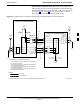
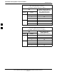
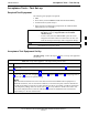
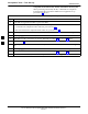
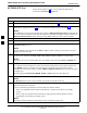
Table Of Contents
- Contents
- Chapter 1 Introduction
- Chapter 2 Preliminary Operations
- Chapter 3 Optimization/Calibration
- Introduction to Optimization and Calibration
- Preparing the LMF
- Overview of Packet BTS files
- LMF Features and Installation Requirements
- LMF File Structure Overview
- LMF Home Directory
- NECF Filename Conventions and Directory Location
- LMF Installation and Update Procedures
- Copy BTS and CBSC CDF (or NECF) Files to the LMF Computer
- Creating a Named HyperTerminal Connection for MMI Communication
- Span Lines - Interface and Isolation
- LMF to BTS Connection
- Using the LMF
- Pinging the Processors
- Download the BTS
- CSM System Time - GPS & LFR/HSO Verification
- Test Equipment Set-up
- Test Set Calibration
- Background
- Calibration Procedures Included
- GPIB Addresses
- Selecting Test Equipment
- Manually Selecting Test Equipment in a Serial Connection Tab
- Automatically Selecting Test Equipment in the Serial Connection Tab
- Calibrating Test Equipment
- Calibrating Cables Overview
- Calibrating Test Cabling using Communications System Analyzer
- Calibrate Test Cabling Using Signal Generator & Spectrum Analyzer
- Setting Cable Loss Values
- Setting TX Coupler Loss Value
- Bay Level Offset Calibration
- Purpose of Bay Level Offset Calibration
- What is BLO Calibration?
- Component Verification During Calibration
- When to Calibrate BLOs
- BLO Calibration Data File
- Test Equipment Setup for RF Path Calibration
- Transmit (TX) Path Calibration Description
- TX Calibration and the LMF
- TX Calibration
- All Cal/Audit and TX Calibration Procedure
- Download BLO Procedure
- Calibration Audit Introduction
- TX Path Audit
- TX Audit Test
- Create CAL File
- RFDS Set-up and Calibration
- Alarms Testing
- Chapter 4 Automated Acceptance Test Procedures

Acceptance Tests – Test Set–up
68P64115A18–1
Mar 2003
1X SC 4812T Lite BTS Optimization/ATP Software Release R2.16.1.x
DRAFT
4-8
Companion frame All TX/RX, All RX, and FER for Diversity RX –
When performing All TX/RX, All RX, or FER ATP for companion
frame diversity RX, perform the additional test equipment set–up
procedures in Table 4-4.
Table 4-4: Additional Diversity RX Test Set–up for Companion Frames
Step Action
1 If the LMF is logged into the BTS, log out of the BTS.
2 If the inter–frame diversity RX cabling to a collocated companion frame is:
S Connected to the companion frame under test, proceed to step 3.
S Disconnected from the companion frame under test, proceed to step 7.
3 For companion frames with inter–frame diversity RX cables connected, click on the LMF Login tab.
4 In the Equipage Information box, select MPC from the Multi–Channel Preselector picklist.
5 Make RX test cable connections for diversity RX FER according to Figure 4-1 and Table 4-1.
6 Proceed to step 10.
7 For companion frames with inter–frame diversity RX cables disconnected, click on the LMF Login
tab.
8 In the Equipage Information box, select EMPC from the Multi–Channel Preselector picklist.
9 Make RX test cable connections for diversity RX FER according to Figure 4-1 and Table 4-2.
10 Click on the LMF BTS# tab, and return to the procedure for the ATP being performed.
4