
User's Manual
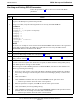
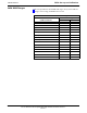
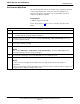
Table Of Contents
- Contents
- Chapter 1 Introduction
- Chapter 2 Preliminary Operations
- Chapter 3 Optimization/Calibration
- Introduction to Optimization and Calibration
- Preparing the LMF
- Overview of Packet BTS files
- LMF Features and Installation Requirements
- LMF File Structure Overview
- LMF Home Directory
- NECF Filename Conventions and Directory Location
- LMF Installation and Update Procedures
- Copy BTS and CBSC CDF (or NECF) Files to the LMF Computer
- Creating a Named HyperTerminal Connection for MMI Communication
- Span Lines - Interface and Isolation
- LMF to BTS Connection
- Using the LMF
- Pinging the Processors
- Download the BTS
- CSM System Time - GPS & LFR/HSO Verification
- Test Equipment Set-up
- Test Set Calibration
- Background
- Calibration Procedures Included
- GPIB Addresses
- Selecting Test Equipment
- Manually Selecting Test Equipment in a Serial Connection Tab
- Automatically Selecting Test Equipment in the Serial Connection Tab
- Calibrating Test Equipment
- Calibrating Cables Overview
- Calibrating Test Cabling using Communications System Analyzer
- Calibrate Test Cabling Using Signal Generator & Spectrum Analyzer
- Setting Cable Loss Values
- Setting TX Coupler Loss Value
- Bay Level Offset Calibration
- Purpose of Bay Level Offset Calibration
- What is BLO Calibration?
- Component Verification During Calibration
- When to Calibrate BLOs
- BLO Calibration Data File
- Test Equipment Setup for RF Path Calibration
- Transmit (TX) Path Calibration Description
- TX Calibration and the LMF
- TX Calibration
- All Cal/Audit and TX Calibration Procedure
- Download BLO Procedure
- Calibration Audit Introduction
- TX Path Audit
- TX Audit Test
- Create CAL File
- RFDS Set-up and Calibration
- Alarms Testing
- Chapter 4 Automated Acceptance Test Procedures

RFDS Set–up and Calibration
68P64115A18–1
Mar 2003
1X SC 4812T Lite BTS Optimization/ATP Software Release R2.16.1.x
DRAFT
3-100
Table 3-39: RFDS Parameter Settings
Step Action
5g – Click OK to close the status report window.
5h – Click on the MGLI.
5i – Click on Device in the BTS menu bar, and select Enable from the pull–down menu.
–– A status report window shows the status of the operation.
5j
– When the operation is complete, click OK to close the status report window.
! CAUTION
When the MGLI changes to INS_ACT, data will automatically be downloaded to the RFDS. During
this process, the RFDS LED will slowly begin flashing red and green for approximately 2–3 minutes.
DO NOT attempt to perform any functions with the RFDS until the LED remains steady green.
5k – Re–seat the redundant GLI card into the backplane connectors and lock it in place with the ejector
tabs.
5l – Once the redundant GLI initializes, download data to it by selecting the card and, in the BTS
menu bar, clicking Device and selecting Download > Data from the pull–down menus.
6 Any MCCs that were INS_ACT when the MGLI was disabled must be disabled, downloaded with
data, and re–enabled as follows:
6a – Select the devices to be reset by clicking on them or using Select from the BTS menu bar and
clicking on MCCs in the pull–down menu.
6b – In the BTS menu bar, click on Device and select Disable from the pull–down menu.
–– A status report window shows the status of the operation.
6c – Click OK to close the status report window.
6d – Repeat Step 6a to select the MCCs.
6e – Click on Device in the BTS menu bar and select Download > Data from the pull–down menu.
(Selected devices do not change colot when data is downoaded.)
– A status report window shows the status of the download.
6f – Click on OK to close the status report window.
6g – When data download is complete, enable the MCCs by following the procedure in Table 3-17.
7 Click on the RFDS tab.
8 Status the RFDS TSU by performing the following:
8a – Click on the SUA to select it.
8b – Click on TSU in the BTS menu bar, and select Status TSU from the pull–down menu.
–– A status report shows the software version number for the TSIC and SUA.
. . . continued on next page