
User's Manual
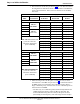
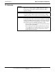
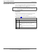
Table Of Contents
- Contents
- Chapter 1 Introduction
- Chapter 2 Preliminary Operations
- Chapter 3 Optimization/Calibration
- Introduction to Optimization and Calibration
- Preparing the LMF
- Overview of Packet BTS files
- LMF Features and Installation Requirements
- LMF File Structure Overview
- LMF Home Directory
- NECF Filename Conventions and Directory Location
- LMF Installation and Update Procedures
- Copy BTS and CBSC CDF (or NECF) Files to the LMF Computer
- Creating a Named HyperTerminal Connection for MMI Communication
- Span Lines - Interface and Isolation
- LMF to BTS Connection
- Using the LMF
- Pinging the Processors
- Download the BTS
- CSM System Time - GPS & LFR/HSO Verification
- Test Equipment Set-up
- Test Set Calibration
- Background
- Calibration Procedures Included
- GPIB Addresses
- Selecting Test Equipment
- Manually Selecting Test Equipment in a Serial Connection Tab
- Automatically Selecting Test Equipment in the Serial Connection Tab
- Calibrating Test Equipment
- Calibrating Cables Overview
- Calibrating Test Cabling using Communications System Analyzer
- Calibrate Test Cabling Using Signal Generator & Spectrum Analyzer
- Setting Cable Loss Values
- Setting TX Coupler Loss Value
- Bay Level Offset Calibration
- Purpose of Bay Level Offset Calibration
- What is BLO Calibration?
- Component Verification During Calibration
- When to Calibrate BLOs
- BLO Calibration Data File
- Test Equipment Setup for RF Path Calibration
- Transmit (TX) Path Calibration Description
- TX Calibration and the LMF
- TX Calibration
- All Cal/Audit and TX Calibration Procedure
- Download BLO Procedure
- Calibration Audit Introduction
- TX Path Audit
- TX Audit Test
- Create CAL File
- RFDS Set-up and Calibration
- Alarms Testing
- Chapter 4 Automated Acceptance Test Procedures

Bay Level Offset Calibration
68P64115A18–1
Mar 2003
1X SC 4812T Lite BTS Optimization/ATP Software Release R2.16.1.x
DRAFT
3-90
Test Pattern Drop–down Pick List
The Tests > TX > TX Calibration... menu window has a Test Pattern
pull–down menu. This menu has the following choices:
S Standard – performs calibration or audit using pilot, paging, synch,
and six traffic channels with IS–97–specified gain. This pattern setting
should be used for all non–in–service calibrations and audits. Using
this pattern setting requires the selection of both a BBX and at least
one MCC.
S Pilot (default) – performs calibration using only the pilot channel.
This pattern setting should be used for in–service calibrations, and
requires selection of only a BBX.
S CDFPilot – This pattern setting is for advanced users. It performs
calibration or audit using the CDF value for pilot gain and IS–97 gain
values for all the other channels included in the Standard pattern
setting (paging, synch, and six traffic). Using this pattern setting
requires the selection of both a BBX and at least one MCC.
S CDF – This pattern setting is for advanced users who need to use
CDF gain settings for all channels included in the Standard pattern
setting (pilot, paging, synch, and six traffic). Using this pattern setting
requires the selection of both a BBX and at least one MCC.
Test Pattern Channels and Gain Settings – The CDMA channels and
their respective digital gain settings used for each test pattern are listed
in Table 3-34.
Table 3-34: Test Patterns with Channels and Gain Settings Used
Test Pattern Channel(s) Gain Setting
Pilot Pilot channel only 541
Standard
Pilot 117
Synch channel (SCH) 57
Paging (PCH) 114
Traffic (TCH) 80 for each of 6 Walsh codes
used (6*80)
CDF Pilot
Pilot Uses CDF–specified pilot
gain
SCH 57
PCH 114
TCH 6*80
CDF
Pilot
All channels use
CDF ifi d i
SCH
CDF–specified gains
PCH
TCH (6)