
User's Manual
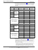
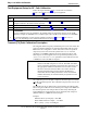
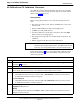
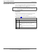
Table Of Contents
- Contents
- Chapter 1 Introduction
- Chapter 2 Preliminary Operations
- Chapter 3 Optimization/Calibration
- Introduction to Optimization and Calibration
- Preparing the LMF
- Overview of Packet BTS files
- LMF Features and Installation Requirements
- LMF File Structure Overview
- LMF Home Directory
- NECF Filename Conventions and Directory Location
- LMF Installation and Update Procedures
- Copy BTS and CBSC CDF (or NECF) Files to the LMF Computer
- Creating a Named HyperTerminal Connection for MMI Communication
- Span Lines - Interface and Isolation
- LMF to BTS Connection
- Using the LMF
- Pinging the Processors
- Download the BTS
- CSM System Time - GPS & LFR/HSO Verification
- Test Equipment Set-up
- Test Set Calibration
- Background
- Calibration Procedures Included
- GPIB Addresses
- Selecting Test Equipment
- Manually Selecting Test Equipment in a Serial Connection Tab
- Automatically Selecting Test Equipment in the Serial Connection Tab
- Calibrating Test Equipment
- Calibrating Cables Overview
- Calibrating Test Cabling using Communications System Analyzer
- Calibrate Test Cabling Using Signal Generator & Spectrum Analyzer
- Setting Cable Loss Values
- Setting TX Coupler Loss Value
- Bay Level Offset Calibration
- Purpose of Bay Level Offset Calibration
- What is BLO Calibration?
- Component Verification During Calibration
- When to Calibrate BLOs
- BLO Calibration Data File
- Test Equipment Setup for RF Path Calibration
- Transmit (TX) Path Calibration Description
- TX Calibration and the LMF
- TX Calibration
- All Cal/Audit and TX Calibration Procedure
- Download BLO Procedure
- Calibration Audit Introduction
- TX Path Audit
- TX Audit Test
- Create CAL File
- RFDS Set-up and Calibration
- Alarms Testing
- Chapter 4 Automated Acceptance Test Procedures

Bay Level Offset Calibration
68P64115A18–1
Mar 2003
1X SC 4812T Lite BTS Optimization/ATP Software Release R2.16.1.x
DRAFT
3-88
Test Equipment Setup for RF Path Calibration
Follow the steps outlined in Table 3-33 and refer as needed to
Figure 3-14 or Figure 3-15 to set up test equipment.
Table 3-33: Set Up Test Equipment for RF Path Calibration
Step Action
1 If it has not already been done, refer to the procedure in Table 3-5 (on page 3-17) to interface the LMF
computer terminal to the frame LAN A connector.
2 If it has not already been done, refer to Table 3-6 (on page 3-26) to start a GUI LMF session.
3 If required, calibrate the test equipment per the procedure in Table 3-25 (on page 3-76).
! CAUTION
To prevent damage to the test equipment, all transmit (TX) test connections must be via the 30 dB
directional coupler for 800 MHz or via a 30 dB coupler with a 20 dB in–line attenuator for 1900 MHz.
4 For TX path calibration, connect the test equipment as shown in Figure 3-14, Figure 3-15, or
Figure 3-16, depending on the communications analyzer being used.
Transmit (TX) Path Calibration Description
The assigned channel frequency and desired power level at the frame TX
ports for transmit calibration are derived from the BTS CDF file. Each
BBX at the site is assigned to a sector and carrier. These are specified
respectively in the sector and carrier fields of the
ParentCARRIER
parameter in each BBXs CDF file block. The channel frequency and
desired power for the assigned sector are specified respectively in the
ChannelList and SIFPilotPwr parameters of the CDF block for the
CARRIER to which the BBX is assigned.
NOTE
Be sure the bts–#.cdf (or bts–#.necf) and cbsc–#.cdf files
loaded on the LMF computer are current. The LMF will obtain
carrier and channel information from these files and insert it into
the appropriate CDMA Test Parameter screen. Failure to have
the most current files from the CBSC can result in incorrect
channel information being used to calibrate the BTS and
unfavorable affects on BTS performance. Carrier and channel
numbers should only be entered manually for special test cases
or as a last resort.
The calibration process attempts to adjust the measured power to within
+
0.5 dB of the desired power. The calibration will pass if the error is less
than +
1.5 dB.
The TX BLO for the SC 4812T Lite is approximately 42.0 dB ±5.0 dB.
BLO is the gain in dB between the known power output of the BBX and
the measured power at the TX port. BLO is derived by deducting the
known BBX power output from the power measured at the TX port or
(Measured Power) – (BBX TX Power Output).
Example:
Measured Power (at TX port) = 36.0 dBm
Known BBX TX Power Output = –6.0 dBm
BLO = (36.0) – (–6.0) = 42.0 dB gain