
User's Manual
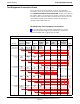
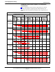
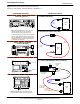
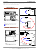
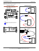
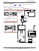
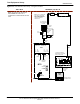
Table Of Contents
- Contents
- Chapter 1 Introduction
- Chapter 2 Preliminary Operations
- Chapter 3 Optimization/Calibration
- Introduction to Optimization and Calibration
- Preparing the LMF
- Overview of Packet BTS files
- LMF Features and Installation Requirements
- LMF File Structure Overview
- LMF Home Directory
- NECF Filename Conventions and Directory Location
- LMF Installation and Update Procedures
- Copy BTS and CBSC CDF (or NECF) Files to the LMF Computer
- Creating a Named HyperTerminal Connection for MMI Communication
- Span Lines - Interface and Isolation
- LMF to BTS Connection
- Using the LMF
- Pinging the Processors
- Download the BTS
- CSM System Time - GPS & LFR/HSO Verification
- Test Equipment Set-up
- Test Set Calibration
- Background
- Calibration Procedures Included
- GPIB Addresses
- Selecting Test Equipment
- Manually Selecting Test Equipment in a Serial Connection Tab
- Automatically Selecting Test Equipment in the Serial Connection Tab
- Calibrating Test Equipment
- Calibrating Cables Overview
- Calibrating Test Cabling using Communications System Analyzer
- Calibrate Test Cabling Using Signal Generator & Spectrum Analyzer
- Setting Cable Loss Values
- Setting TX Coupler Loss Value
- Bay Level Offset Calibration
- Purpose of Bay Level Offset Calibration
- What is BLO Calibration?
- Component Verification During Calibration
- When to Calibrate BLOs
- BLO Calibration Data File
- Test Equipment Setup for RF Path Calibration
- Transmit (TX) Path Calibration Description
- TX Calibration and the LMF
- TX Calibration
- All Cal/Audit and TX Calibration Procedure
- Download BLO Procedure
- Calibration Audit Introduction
- TX Path Audit
- TX Audit Test
- Create CAL File
- RFDS Set-up and Calibration
- Alarms Testing
- Chapter 4 Automated Acceptance Test Procedures

Test Equipment Set-up
68P64115A18–1
Mar 2003
1X SC 4812T Lite BTS Optimization/ATP Software Release R2.16.1.x
DRAFT
3-56
Supported Test Equipment
CAUTION
To prevent damage to the test equipment, all transmit (TX) test
connections must be through a 30 dB directional coupler plus a
20 dB in-line attenuator for both the 800 MHz and 1.9 GHz
BTSs.
IS–95A/B Operation
Optimization and ATP testing for IS–95A/B sites or carriers may be
performed using the following test equipment:
S CyberTest
S Advantest R3267 spectrum analyzer with R3562 signal generator
S Advantest R3465 spectrum analyzer with R3561L signal generator
and HP–437B or Gigatronics Power Meter
S Agilent E4406A transmitter test set with E4432B signal generator
S Agilent 8935 series E6380A communications test set (formerly HP
8935)
S Hewlett–Packard HP 8921 (with CDMA interface and, for 1.9 GHz,
PCS Interface) and HP–437B or Gigatronics Power Meter
S Spectrum Analyzer (HP8594E) – optional
S Rubidium Standard Timebase – optional
CDMA2000 1X Operation
Optimization and ATP testing for CDMA2000 1X sites or carriers may
be performed using the following test equipment:
S Advantest R3267 spectrum analyzer with R3562 signal generator
S Agilent E4406A transmitter test set with E4432B signal generator
S Agilent 8935 series E6380A communications test set (formerly HP
8935) with option 200 or R2K and with E4432B signal generator for
1X FER
Test Equipment Preparation
See Appendix F for specific steps to prepare each type of test set and
power meter to perform calibration and ATP .