
User's Manual
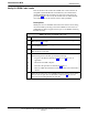
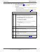
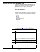
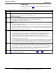
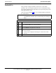
Table Of Contents
- Contents
- Chapter 1 Introduction
- Chapter 2 Preliminary Operations
- Chapter 3 Optimization/Calibration
- Introduction to Optimization and Calibration
- Preparing the LMF
- Overview of Packet BTS files
- LMF Features and Installation Requirements
- LMF File Structure Overview
- LMF Home Directory
- NECF Filename Conventions and Directory Location
- LMF Installation and Update Procedures
- Copy BTS and CBSC CDF (or NECF) Files to the LMF Computer
- Creating a Named HyperTerminal Connection for MMI Communication
- Span Lines - Interface and Isolation
- LMF to BTS Connection
- Using the LMF
- Pinging the Processors
- Download the BTS
- CSM System Time - GPS & LFR/HSO Verification
- Test Equipment Set-up
- Test Set Calibration
- Background
- Calibration Procedures Included
- GPIB Addresses
- Selecting Test Equipment
- Manually Selecting Test Equipment in a Serial Connection Tab
- Automatically Selecting Test Equipment in the Serial Connection Tab
- Calibrating Test Equipment
- Calibrating Cables Overview
- Calibrating Test Cabling using Communications System Analyzer
- Calibrate Test Cabling Using Signal Generator & Spectrum Analyzer
- Setting Cable Loss Values
- Setting TX Coupler Loss Value
- Bay Level Offset Calibration
- Purpose of Bay Level Offset Calibration
- What is BLO Calibration?
- Component Verification During Calibration
- When to Calibrate BLOs
- BLO Calibration Data File
- Test Equipment Setup for RF Path Calibration
- Transmit (TX) Path Calibration Description
- TX Calibration and the LMF
- TX Calibration
- All Cal/Audit and TX Calibration Procedure
- Download BLO Procedure
- Calibration Audit Introduction
- TX Path Audit
- TX Audit Test
- Create CAL File
- RFDS Set-up and Calibration
- Alarms Testing
- Chapter 4 Automated Acceptance Test Procedures

Download the BTS
68P64115A18–1
Mar 2003
1X SC 4812T Lite BTS Optimization/ATP Software Release R2.16.1.x
DRAFT
3-38
Verify GLI ROM Code Loads
Devices should not be loaded with a RAM code version which is not
compatible with the ROM code with which they are loaded. Before
downloading RAM code and data to the processor cards, follow the
procedure in Table 3-12 to verify the GLI devices are loaded with the
correct ROM code for the software release used by the BSS.
Prerequisite
Identify the correct GLI ROM code load for the software release being
used on the BSS by referring to the Version Matrix section of the SCt
CDMA Release Notes (supplied on the tapes or CD–ROMs containing
the BSS software).
Table 3-12: Verify GLI ROM Code Loads
Step Action
1 If it has not already been done, start a GUI LMF session and log into the
BTS ( refer to Table 3-6).
2 Select all GLI devices by clicking on them, and select Device > Status
from the BTS menu bar.
3 In the status report window which opens, note the number in the ROM
Ver column for each GLI2.
4 If the ROM code loaded in the GLIs is not the correct one for the software
release being used on the BSS, perform the following:
4a – Log out of the BTS as described in Table 3-8 or Table 3-9, as
applicable.
4b – Disconnect the LMF computer.
4c – Reconnect the span lines as described in Table 5-7.
4d – Have the CBSC download the correct ROM code version to the BTS
devices.
5 When the GLIs have the correct ROM load for the software release being
used, be sure the span lines are disabled as outlined in Table 3-4 and
proceed to downloading RAM code and data.