
User's Manual

Module Front Panel LED Indicators and Connectors68P64115A18–1
Mar 2003
1X SC 4812T Lite BTS Optimization/ATP Software Release R2.16.1.x
DRAFT
6-31
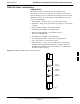
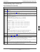
GLI2 LED Status Combinations
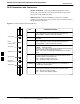
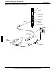
The GLI2 module indicators, controls, and connectors are described
below and shown in Figure 6-3.
The indicators and controls consist of:
S Four LEDs
S One pushbutton
ACTIVE LED
Solid GREEN – GLI2 is active. This means that the GLI2 has shelf
control and is providing control of the digital interfaces.
Off – GLI2 is not active (i.e., Standby). The mate GLI2 should be
active.
MASTER LED
S Solid GREEN – GLI2 is Master (sometimes referred to as MGLI2).
S Off – GLI2 is non-master (i.e., Slave).
ALARM LED
S Solid RED – GLI2 is in a fault condition or in reset.
S While in reset transition, STATUS LED is OFF while GLI2 is
performing ROM boot (about 12 seconds for normal boot).
S While in reset transition, STATUS LED is ON while GLI2 is
performing RAM boot (about 4 seconds for normal boot).
S Off – No Alarm.
STATUS LED
S Flashing GREEN– GLI2 is in service (INS), in a stable operating
condition.
S On – GLI2 is in OOS RAM state operating downloaded code.
S Off – GLI2 is in OOS ROM state operating boot code.
SPANS LED
S Solid GREEN – Span line is connected and operating.
S Solid RED – Span line is disconnected or a fault condition exists.
6