
User's Manual

Troubleshooting: RFDS
68P64115A18–1
Mar 2003
1X SC 4812T Lite BTS Optimization/ATP Software Release R2.16.1.x
DRAFT
6-26
Troubleshooting: RFDS
Introduction
The RFDS is used to perform Pre–Calibration Verification and
Post-Calibration Audits which limit-check the RFDS-generate and
reported receive levels of every path from the RFDS through the
directional coupler coupled paths. In the event of test failure, refer to the
following tables.
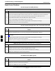
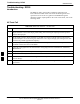
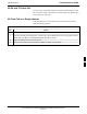
All Tests Fail
Table 6-29: RFDS Fault Isolation – All Tests Fail
Step Action
1 Check the TX calibration equipment for proper operation by manually setting the signal generator
output attenuator to the lowest output power setting and connecting the output port to the spectrum
analyzer RF input port.
2 Set the signal generator output attenuator to –90 dBm, and switch on the RF output. Verify that the
spectrum analyzer can receive the signal, indicate the correct signal strength, (accounting for the cable
insertion loss), and the approximate frequency.
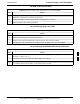
3 Visually inspect RF cabling. Make sure each directional coupler forward and reflected port connects to
the RFDS antenna select unit on the RFDS.
4 Check the wiring against the site documentation wiring diagram or the SC4812ET Lite Installation;
68P09253A36.
5 Verify any changes to the RFDS parameter settings have been downloaded.
6 Status the TSU to verify the TSIC and SUA software versions are correct.
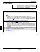
7 Check to see that all RFDS boards show green on the front panel LED indicators. Visually check for
external damage.
8 If any board LEDs do not show green, replace the RFDS with a known–good unit. Re–test after
replacement.
6