
User's Manual

Basic Troubleshooting: RF Path Fault Isolation68P64115A18–1
Mar 2003
1X SC 4812T Lite BTS Optimization/ATP Software Release R2.16.1.x
DRAFT
6-13
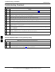
Single–Sided BLO Checkbox
When performing a calibration with the TX Calibration... or All
Cal/Audit... functions, the Single–Sided BLO checkbox should not be
checked when the redundant BBX is being calibrated. When a
calibration fails with the redundant BBX selected, try re–running the
calibration with the Single–Sided BLO checkbox unchecked. If the
calibration still fails, refer to the following paragraphs and use the TX
output fault isolation flowchart to identify the most probable cause of the
failure.
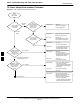
If Faults Are Isolated
If the fault reports are isolated between successful path checks, the root
cause of the faults most likely lies with one or more of the Field
Replaceable Unit (FRU) modules. If more than one failure was reported,
look for a common denominator in the data. For example, if any TX test
fails on one sector only, the BBX assigned to that sector (Table 1-6) is a
likely cause. Also, look at the severity of the failure. If the path loss is
just marginally out of the relaxed specification limit during the
post-calibration TX audit, suspect excessive cable loss. If limits are
missed by a wide margin, suspect mis–wired cables or total device
failure. Use the TX output fault isolation flowchart in Figure 6-1 to
identify the strongest possible cause for a failed TX test.
Fault Isolation Flowchart
The flowchart covers the transmit path. Transmit paths usually fail the
lower test limit, indicating excessive loss in some component in the BTS
site or mis–wiring. A failure of an upper limit usually indicates a
problem with the test setup or external equipment. Before replacing a
suspected FRU, always repeat and verify the test results to rule out a
transient condition. If a BBX fails an upper limit in the post–calibration
audit procedure, re–calibrate and verify the out–of–tolerance condition
for that BBX and/or sector before replacement.
Flowchart Prerequisites
Before entering the fault isolation sequence outlined in the flowchart, be
sure the following have been completed:
S GLIs, MCCs, and BBXs have been downloaded with the correct ROM
code, RAM code, and data (Table 3-12, Table 3-13, and Table 3-14).
S MGLI, CSMs, and MCCs are enabled (Table 3-13, Table 3-16, and
Table 3-17, respectively)
S Be sure the LED on the correct CCD card is solid green.
S Be sure no alarms are being reported by opening an LMF alarm
window as outlined in Table 3-47.
6