
User's Manual

Basic Troubleshooting: RF Path Fault Isolation
68P64115A18–1
Mar 2003
1X SC 4812T Lite BTS Optimization/ATP Software Release R2.16.1.x
DRAFT
6-12
Basic Troubleshooting: RF Path Fault Isolation
Overview
The optimization (RF path characterization or calibration) and
post-calibration (audit) procedures measure and limit-check the BTS
reported transmit and receive levels of the path from each BBX to the
back of the frame. When a fault is detected, it is specific to a receive or
transmit path. The troubleshooting process in this section determines the
most probable cause of the fault.
As the calibration and audit tests are performed, results are displayed in
the LMF test status report window. When faults are encountered, the test
procedure in progress continues running and displaying any further
faults. If it appears that there are major faults, the test can be aborted.
The test results can be saved to a
bts–#.rpt file in the<x>:\<lmf home
directory
\cdma\bts–# folder. To do this, close the test status report
window using the Save Results button.
NOTE
Closing the test status report window with the Dismiss button
will delete the test results without saving them.
If a test is re–run or a new calibration, audit, or test is run and the results
are saved, the previous test results in the
bts–#.rpt file are
overwritten. To prevent losing previous test results in the
bts–#.rpt
file, refer to the procedure in Table 4-13 before performing further
testing with the LMF.
If there are major faults, recheck the test equipment attachments for
errors. If none are found, close the test status report window using the
Save Results button, and save the contents of the resulting
bts–#.rpt
file as described in Table 4-13. Also, note other specifics about the
failure, and proceed with the fault isolation procedure.
If Every Test Fails
Check the calibration equipment for proper operation by manually
setting the signal generator output attenuator to the lowest output power
setting. Connect the output port to the spectrum analyzer RF input port.
Set the signal generator output attenuator to –90 dBm, and switch on the
RF output. Verify that the spectrum analyzer can receive the signal,
indicate the correct signal strength (accounting for the cable insertion
loss), and indicate the approximate frequency.
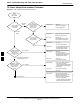
Verify BLO Checkbox
When performing a calibration with the TX Calibration... or All
Cal/Audit... functions, the Verify BLO checkbox should normally be
checked. When a calibration fails, determine if any items such as
directional couplers or combiners have been added to the TX path. If
additional items have been installed in the path, try re–running the
calibration with Verify BLO unchecked. If calibration still does not
pass, refer to the following paragraphs and use the TX output fault
isolation flowchart to identify the most probable cause of the failure.
6