
User's Manual


Power Delta Calibration68P64115A18–1
Mar 2003
1X SC 4812T Lite BTS Optimization/ATP Software Release R2.16.1.x
DRAFT
H-13
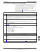
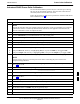
Table H-4: HP8921A Power Delta Calibration Procedure
Step Action
9 Set the measuring HP8921A as follows:
– Measure mode to CDMA Anl
– Frequency to the CDMA calibration target frequency
– Input Attenuation to 0 dB
– Input port to RF–IN
– Gain to Auto
– Analyzer Direction to Fwd
10 Turn on the source HP8921A signal output.
11 Measure and record the channel power reading on the measuring HP8921A as result
B ________________________.
12 Turn off the source HP8921A signal output and disconnect the equipment.
13 Compute the delta between HP437 and HP8921A using the following formula:
Delta = A – B
Example: Delta = –0.70 dBm – (–1.25 dBm) = 0.55 dBm
Example: Delta = 0.26 dBm – 0.55 dBm = –0.29 dBm
These examples are included to show the mathematics and do not represent actual readings.
NOTE
Add this delta value to the TX Cable Loss value during In–Service Calibration (see Step 4 in
Table H-6).
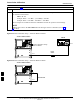
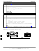
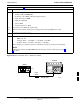
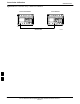
Figure H-8: Delta Calibration Setup – HP8921A to HP437
Short RF Cable
HP 8921A
DUPLEX
OUT
HP437B
Power
Sensor
SENSOR
FW00801
H