
User's Manual


Power Delta Calibration
68P64115A18–1
Mar 2003
1X SC 4812T Lite BTS Optimization/ATP Software Release R2.16.1.x
DRAFT
H-6
Advantest R3267 Power Delta Calibration
The Advantest R3267 spectrum analyzer and R3562 signal generator test
equipment combination can be used for ISC of IS–2000 CDMA 1X as
well as IS–95A/B operation modes. The power delta calibration is
performed on the R3267. After the offset value has been calculated, add
it to the TX cable loss value.
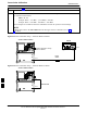
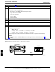
Preliminary Advantest Test Equipment Set–up
To provide proper operation during power delta calibration, be sure the
R3267 is connected to the R3562 as shown in Figure F-17.
Power Delta Calibration
Follow the procedure in Table H-2 to perform the Advantest R3267
Power Delta Calibration procedure.
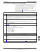
Table H-2: Advantest R3267 Power Delta Calibration Procedure
Step Action
1
NOTE
Warm-up test equipment for a minimum of 60 minutes prior to this procedure. After it is warmed up
and stabilized, calibrate the test equipment as described in the “Test Set Calibration” section of
Chapter NO TAG.
Be sure the R3267 and R3562 are connected as shown in Figure F-17.
2 Press the SHIFT and the PRESET keys located on the right side of the control panel.
3 Press the ADVANCE key in the MEASUREMENT area of the control panel.
4 On the CRT, select RX Control by pressing ACTIVE key 1.
5 On the CRT, select Frequency Setup by pressing ACTIVE key 3.
6 On the CRT, highlight Frequency by adjusting the DISPLAY CONTROL knob.
7 Press FREQ key in the ENTRY section of the control panel.
8 Set the frequency to the desired value using the keypad ENTRY section keys.
9 Press the LEVEL key in the ENTRY section of the control panel.
10 Set the level to 0 dBm using the keypad ENTRY section keys.
11 On the CRT, verify OFF is highlighted in Modulation, if not press the ACTIVE key 5 to toggle it
OFF.
12 On the CRT, verify OFF is highlighted in Output, if not press the ACTIVE key 6 to toggle it OFF.
13
Zero the Power Meter prior to connecting the power sensor to the RF cable from the signal generator.
NOTE
For best accuracy, always re–zero the power meter before connecting the power sensor to the
component being calibrated.
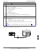
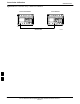
14 Connect the RF cable from the R3562 signal generator RF OUT port to the power sensor, refer to
Figure H-4.
15 On the R3562 CRT, set the Output to ON by pressing ACTIVE key 6.
. . . continued on next page
H