
User's Manual

Test Equipment Inter–unit Connection, Testing, and Control
68P64115A18–1
Mar 2003
1X SC 4812T Lite BTS Optimization/ATP Software Release R2.16.1.x
DRAFT
F-20
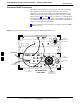
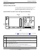
Advantest R3465 Connection
The following diagram depicts the rear panels of the Advantest R3465
test equipment as configured to perform automatic tests. All test
equipment is controlled by the LMF via an IEEE–488/GPIB bus. The
LMF expects each piece of test equipment to have a factory-set GPIB
address (refer to Table F-6 and Figure F-7). If there is a communications
problem between the LMF and any piece of test equipment, verify that
the GPIB addresses have been set correctly and that the GPIB cables are
firmly connected to the test equipment.
Figure F-13 shows the connections when not using an external 10 MHz
Rubidium reference.
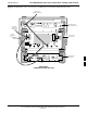
Figure F-13: Cable Connections for Test Set without 10 MHz Rubidium Reference
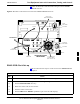
ADVANTEST R3465
REAR PANEL
GPIB
CONNECTOR
SERIAL I/O
LOCAL IN
SERIAL I/O
SYN REF IN
10 MHZ OUT
PARALLEL
EXT TRIGGER
10 MHZ REF
GATE IN
GPIB
CDMA CLOCK OUT
AC POWER
AC POWER
R3561L
REAR PANEL
R3465
REAR PANEL
TO T–CONNECTOR
ON FRONT PANEL
(EVEN/SEC/SYNC IN)
X
YZ
IF OUT
421 MHZ
TO POWER METER
GPIB CONNECTOR
TO GPIB
INTERFACE BOX
FW00370
F