
User Manual


FRU Optimization/ATP Test Matrix
Jan 2002
B-1
SC4812ET BTS Optimization/ATP — CDMA LMF
Usage & Background
Periodic maintenance of a site may also mandate re–optimization of
specific portions of the site. An outline of some basic guidelines is
included in the following tables.
Re–optimization steps listed for any assembly detailed in
the tables below must be performed anytime an RF cable
associated with it is replaced.
IMPORTANT
*
Detailed Optimization/ATP
Test Matrix
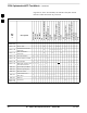
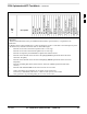
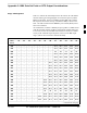
Table B-1 outlines in more detail the tests that would need to be
performed if one of the BTS components were to fail and be replaced. It
is also assumes that all modules are placed OOS–ROM via the LMF
until full redundancy of all applicable modules is implemented.
The following guidelines should also be noted when using this table.
Not every procedure required to bring the site back in
service is indicated in Table B-1. It is meant to be used as a
guideline ONLY. The table assumes that the user is familiar
enough with the BTS Optimization/ATP procedure to
understand which test equipment set ups, calibrations, and
BTS site preparation will be required before performing the
Table # procedures referenced.
IMPORTANT
*
Various passive BTS components (such as the DRDCs, filter; etc.) only
require a TX calibration audit to be performed in lieu of a full path
calibration. If the TX path calibration audit fails, the entire RF path
calibration will need to be repeated. If the RF path calibration fails,
further troubleshooting is warranted.
Whenever any C–CCP BACKPLANE is replaced, it is assumed that
only power to the C–CCP shelf being replaced is turned off via the
breaker supplying that shelf.
If any significant change in signal level results from any
component being replaced in the RX or TX signal flow
paths, it would be identified by re–running the RX and TX
calibration audit command.
NOTE
When the CIO is replaced, the C–CCP shelf remains powered up. The
BBX boards may need to be removed, then re–installed into their
B