
User's Manual

Power Delta Calibration
68P09255A69-3
Aug 2002
1X SC4812ET Lite BTS Optimization/ATP Software Release 2.16.1.x
PRELIMINARY
H-12
HP8921A Power Delta Calibration
Use the HP8921A communications test set to measure power during ISC
only for IS-95A and B operation of 800 MHz systems. After the offset
value has been calculated, add it to the TX cable loss value.
Follow the procedure in Table H-4 to perform the HP8921A Power Delta
Calibration procedure.
NOTE
This procedure requires two HP8921A communication test sets.
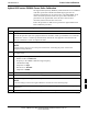
Table H-4: HP8921A Power Delta Calibration Procedure
Step Action
NOTE
Perform this procedure after test equipment has been allowed to warm-up and stabilize for a minimum
of 60 minutes. After it is warmed up and stabilized, calibrate the test equipment as described in the
“Test Set Calibration” section of Chapter NO TAG.
1
Zero the Power Meter prior to connecting the power sensor to the RF cable from the signal generator.
NOTE
For best accuracy, always re-zero the power meter before connecting the power sensor to the
component being calibrated.
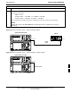
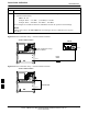
2 Connect a short RF cable between the HP8921A Duplex Out port and the HP437 power sensor (see
Figure H-8).
3 Set the HP8921A signal source as follows:
- Measure mode to CDMA Generator
- Frequency to the CDMA Calibration target frequency
- CW RF Path to IQ
- Output Port to Dupl
- Data Source to Random
- Amplitude to 0 dBm
4 Measure and record the power value reading on the HP437 Power Meter.
5 Record the Power Meter reading as result A ________________________.
6 Turn off the source HP8921A signal output, and disconnect the HP437.
NOTE
Leave the settings on the source HP8921A for convenience in the following steps.
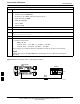
7 Connect the short RF cable between the source HP8921A Duplex Out port and the measuring
HP8921A RF-IN port (see Figure H-9).
8 Ensure that the source HP8921A settings are the same as in Step 3.
. . . continued on next page
H