
User's Manual

Power Delta Calibration68P09255A69-3
Aug 2002
1X SC4812ET Lite BTS Optimization/ATP Software Release 2.16.1.x
PRELIMINARY
H-3
Power Delta Calibration
Introduction
The ISC procedure has several differences from a normal calibration
procedure. One of these is the use of a spectrum
analyzer/communications test set instead of a power meter to measure
power. Power meters are broadband measurement devices and cannot be
used to measure power during ISC because other carriers are operating.
A spectrum analyzer can be used because it measures power at a given
frequency. Measuring power using a spectrum analyzer is less accurate
than using a power meter, therefore, compensation is required for the
accuracy difference (delta) between the power meter and the spectrum
analyzer.
Agilent E4406A Power Delta Calibration
The Agilent E4406A transmitter tester and E4432B signal generator test
equipment combination can be used for ISC of IS-2000 CDMA 1X as
well as IS-95A/B operation modes. The power delta calibration is
performed on the E4406A, but the E4432B is required to generate the
reference signal used to calculate the power delta offset. After the offset
value has been calculated, add it to the TX cable loss value in the LMF.
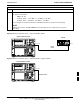
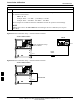
Preliminary Agilent Test Equipment Set-up
To provide proper operation during power delta calibration, be sure the
E4406A and E4432B are connected as shown in Figure F-16.
Power Delta Calibration
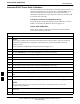
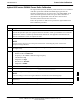
Follow the procedure in Table H-1 to perform the Agilent E4406A
Power Delta Calibration procedure.
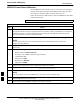
Table H-1: Agilent E4406A Power Delta Calibration Procedure
Step Action
NOTE
Perform this procedure after test equipment has been allowed to warm-up and stabilize for a minimum
of 60 minutes. After it is warmed up and stabilized, calibrate the test equipment as described in the
“Test Set Calibration” section of Chapter NO TAG.
1
Zero the Power Meter prior to connecting the power sensor to the RF cable from the signal generator.
NOTE
For best accuracy, always re-zero the power meter before connecting the power sensor to the
component being calibrated.
2 Be sure the E4406A and E4432B are connected as shown in Figure F-16.
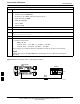
3 Connect a short RF cable from the E4432B RF OUTPUT connector the HP437 power meter power
sensor (see Figure H-1).
. . . continued on next page
H