
User's Manual

Manual Cable Calibration
68P09255A69-3
Aug 2002
1X SC4812ET Lite BTS Optimization/ATP Software Release 2.16.1.x
PRELIMINARY
F-30
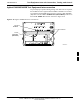
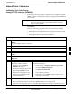
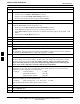
Table F-20: Calibrating Test Cable Setup (using the HP PCS Interface)
Step Action
9 Set the user fixed Attenuation Setting to 0 dBm:
- Position cursor at Analyzer Attenuation and select it
- Position cursor at User Fixed Atten Settings and select it.
- Enter 0 (zero) using the numeric keypad and press [Enter].
10 Select Back to Previous Menu.
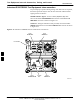
11 Record the HP83236 Generator Frequency Level:
Record the HP83236B Generator Frequency Level:
- Position cursor at Show Frequency and Level Details and select it.
- Under HP83236 Frequencies and Levels, record the Generator Level.
- Under HP83236B Frequencies and Levels, record the Generator Frequency Level (1850 - 1910
MHz).
- Position cursor at Prev Menu and select it.
12 Click on Pause for Manual Measurement.
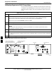
13 Connect the power sensor directly to the RF OUT ONLY port of the PCS Interface.
14 On the HP8921A, under To Screen, select CDMA GEN.
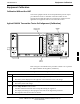
15 Move the cursor to the Amplitude field and click on the Amplitude value.
16
Increase the Amplitude value until the power meter reads 0 dBm ±0.2 dB.
NOTE
The Amplitude value can be increased coarsely until 0 dBM is reached; then fine tune the amplitude
by adjusting the Increment Set to 0.1 dBm and targeting in on 0 dBm.
17
Disconnect the power sensor from the RF OUT ONLY port of the PCS Interface.
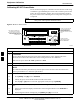
NOTE
The Power Meter sensor’s lower limit is -30 dBm. Thus, only components having losses ≤30 dB
should be measured using this method. For further accuracy, always re-zero the power meter
before connecting the power sensor to the component being calibrated. After connecting the
power sensor to the component, record the calibrated loss immediately.
18 Disconnect all components in the test setup and calibrate each one separately by connecting each
component, one-at-a-time, between the RF OUT ONLY PORT and the power sensor. Record the
calibrated loss value displayed on the power meter.
Example: (A) Test Cable(s) = -1.4 dB
(B) 20 dB Attenuator = -20.1 dB
(B) Directional Coupler = -29.8 dB
19 After all components are calibrated, reassemble all components together and calculate the total test
setup loss by adding up all the individual losses:
Example: Total test setup loss = -1.4 -29.8 -20.1 = -51.3 dB.
This calculated value will be used in the next series of tests.
20 Under Screen Controls press the TESTS button to display the TESTS (Main Menu) screen.
21 Select Continue (K2).
22 Select RF Generator Level and set to -119 dBm.
. . . continued on next page
F