
User's Manual


Test Equipment Preparation
08/01/2001
F-1
1X SCt4812ET Lite BTS Optimization/ATP
PRELIMINARY
Purpose
This appendix provides information on setting up the HP8921 with PCS
interface, the HP8935, the Advantest R3465, and the HP437 and
Gigatronics 8542 power meters. The Cybertest test set doesn’t require
any setup.
HP8921A Test Equipment
Connections
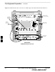
The following diagram depicts the rear panels of the HP 8921A test
equipment as configured to perform automatic tests. All test equipment
is controlled by the LMF via an IEEE–488/GPIB bus. The LMF expects
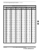
each piece of test equipment to have a factory-set GPIB address (refer to
Table F-4). If there is a communications problem between the LMF and
any piece of test equipment, you should verify that the GPIB addresses
have been set correctly and that the GPIB cables are firmly connected to
the test equipment.
Figure F-1 shows the connections when not using an external 10 MHz
Rubidium reference.
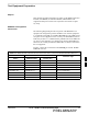
Table F-1: HP8921A/600 Communications Test Set Rear Panel Connections Without Rubidium Reference
From Test Set: To Interface:
8921A 83203B CDMA 83236A PCS
Connector Type
CW RF OUT CW RF IN SMC–female – SMC–female
114.3 MHZ IF OUT 114.3 MHZ IF IN SMC–female – SMC–female
IQ RF IN IQ RF OUT SMC–female – SMC–female
DET OUT AUX DSP IN SMC–female – SMC–female
CONTROL I/O CONTROL I/O 45–pin custom BUS
10 MHZ OUT SYNTH REF IN BNC–male – BNC–male
HPIB INTERFACE HPIB INTERFACE HPIB cable
10 MHZ OUT REF IN BNC–male – BNC–male
F