
User's Manual

RFDS – Fault Isolation
PRELIMINARY
1X SCt4812ET Lite BTS Optimization/ATP
08/01/2001
6-26
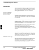
Introduction
The RFDS is used to perform Pre–Calibration Verification and
Post-Calibration Audits which limit-check the RFDS-generate and
reported receive levels of every path from the RFDS through the
directional coupler coupled paths. In the event of test failure, refer to the
following tables.
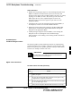
All tests fail
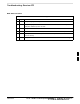
Table 6-27: RFDS Fault Isolation – All tests fail
Step Action
1 Check the calibration equipment for proper operation by manually setting the signal generator output
attenuator to the lowest output power setting and connecting the output port to the spectrum analyzer
rf input port.
2 Set the signal generator output attenuator to –90 dBm, and switch on the rf output. Verify that the
spectrum analyzer can receive the signal, indicate the correct signal strength, (accounting for the cable
insertion loss), and the approximate frequency.
3 Visually inspect RF cabling. Make sure each directional coupler forward and reflected port connects to
the RFDS antenna select unit on the RFDS.
4 Check the wiring against the site documentation wiring diagram or the BTS Site Installation manual.
5 Verify RGLI and TSU have been downloaded.
6 Check to see that all RFDS boards show green on the front panel indicators. Visually check for
external damage.
7 If any boards that do not show green replace the RFDS with a known–good unit. Re–test after
replacement.
All RX and TX paths fail
If every receive or transmit path fails, the problem most likely lies with
the rf converter board or the transceiver board. Replace the RFDS with a
known–good unit and retest.
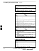
All tests fail on a single
antenna
If all path failures are on one antenna port, forward and/or reflected,
make the following checks.
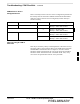
Table 6-28: RFDS Fault Isolation – All tests fail on single antenna path
Step Action
1 Visually inspect the site interface cabinet internal cabling to the suspect directional coupler antenna
port.
2 Verify the forward and reflected ports connect to the correct RFDS antenna select unit positions on the
RFDS backplane. Refer to the installation manual for details.
. . . continued on next page
6