
User's Manual

SCCP Backplane Troubleshooting – continued
08/01/2001
6-21
1X SCt4812ET Lite BTS Optimization/ATP
PRELIMINARY
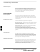
CIO Connectors
S RX RF antenna path signal inputs are routed through RX paths of the
DRDCs or TRDCs at the RF interface panel (rear of frame), and
through coaxial cables to the two MPC modules. The three “A” (main)
signals go to one MPC; the three “B” (diversity) to the other. The
MPC outputs the low–noise–amplified signals via the SCCP
backplane to the CIO where the signals are split and sent to the
appropriate BBX2.
S A digital bus then routes the baseband signal through the BBX2, to
the backplane, and then on to the MCC24/MCC8E slots.
S Digital TX antenna path signals originate at the MCC24/MCC8Es.
Each output is routed from the MCC24/MCC8E slot through the
backplane to the appropriate BBX2.
S TX RF path signal originates from the BBX2, travels through the
backplane to the CIO, through the CIO, and then through
multi-conductor coaxial cabling to the trunking module and LPAs in
the LPA shelf.
SCCP Backplane
Troubleshooting Procedure
The following tables provide standard procedures for troubleshooting
problems that appear to be related to a defective SCCP backplane. The
tables are broken down into possible problems and steps which should
be taken in an attempt to find the root cause.
It is important to note that all steps be followed before
replacing ANY SCCP backplane.
IMPORTANT
*
Digital Control Problems
No GLI2 Control via LMF (all GLI2s)
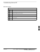
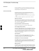
Table 6-17: No GLI2 Control via LMF (all GLI2s)
Step Action
1 Check the Ethernet LAN for proper connection, damage,
shorts, or opens.
2 Be sure the LAN IN and OUT connectors in the power entry
compartment are properly terminated.
3 Be sure the proper IP address is entered in the Network Login
tab of the LMF login screen.
4 Verify SCCP backplane Shelf ID DIP switch is set correctly.
6