
User's Manual

LMF to BTS Connection
PRELIMINARY
1X SCt4812ET Lite BTS Optimization/ATP
08/01/2001
3-20
68P09253A60
LMF to BTS Connection
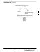
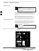
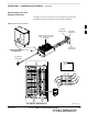
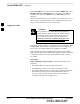
The CDMA LMF computer may be connected to the LAN A or B
connector located behind the frame lower air intake grill. Figure 3-10
below shows the general location of these connectors. LAN A is
considered the primary LAN.
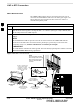
Table 3-6: Connect the LMF to the BTS
Step Action
1 To gain access to the LAN connectors, open the LAN cable and utility shelf access panel, then pull
apart the hook–and–loop fabric covering the BNC “T” connector (see Figure 3-10). If desired, slide
out the utility shelf for the LMF computer.
2
Connect the CDMA LMF computer to the LAN A (left–hand) BNC connector via PCMCIA Ethernet
Adapter.
NOTE
Xircom Model PE3–10B2 or equivalent can also be used to interface the CDMA LMF Ethernet
connection to the BTS frame connected to the PC parallel port, powered by an external AC/DC
transformer. In this case, the BNC cable must not exceed three feet in length.
* IMPORTANT
The LAN shield is isolated from chassis ground. The LAN shield (exposed portion of BNC connector)
must not touch the chassis during optimization.
Á
Á
Á
Á
Á
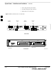
LMF BNC “T” CONNECTIONS
ON LEFT SIDE OF FRAME
(ETHERNET “A” SHOWN;
ETHERNET “B” COVERED
WITH HOOK–AND–LOOP
FABRIC)
LMF COMPUTER
TERMINAL WITH
MOUSE
PCMCIA ETHERNET
ADPATER & ETHERNET
UTP ADAPTER
UNIVERSAL TWISTED
PAIR (UTP) CABLE (RJ11
CONNECTORS)
10BASET/10BASE2
CONVERTER CONNECTS
DIRECTLY TO BNC T
115 VAC POWER
CONNECTION
NOTE:
Open LAN CABLE ACCESS
door. Pull apart hook–and–loop
fabric and gain access to the
LAN A or LAN B LMF BNC
connector.
Figure 3-10: LMF Connection Detail
SC4812ETL0012–2
3