
User's Manual

Span Lines – Interface and Isolation – continued
08/01/2001
3-15
1X SCt4812ET Lite BTS Optimization/ATP
PRELIMINARY
T1/E1 Span Isolation
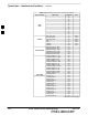
Table 3-4 describes the action required for span isolation.
Table 3-4: T1/E1 Span Isolation
Step Action
1 Have the OMCR/CBSC place the BTS OOS.
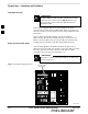
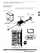
2 To disable the span lines, locate the connector for the span or spans which must be disabled and
remove the respective connector from the applicable SCCP cage Span I/O board (Figure 3-7).
Configure Optional Channel
Service Units
The M–PA T H 537 Channel Service Unit (CSU) module provides
in–band SNMP–managed digital service access to T1 and fractional T1
lines. The M–PAT H 437 Channel Service Unit (CSU) module provides
in–band SNMP–managed digital service access to E1 and fractional E1
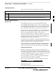
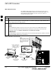
lines. CSU modules units plug into the CSU shelf (see Figure 3-8).
The CSU shelf can support two M–PAT H 537 or two M–PATH 437 CSU
modules. The 537 CSU module supports a single T1 span connection.
The 437 CSU module supports a single E1 span connection.
Remote M–PA T H management is available via SNMP over an in–band
data link on the span line (using a facility data link or 8–64 Kbps of a
DS0 channel). The unit at the near end of the management path can be
an SNMP manager or another M–PAT H CSU.
Programming of the M–PAT H is accomplished through the DCE 9–pin
connector on the front panel of the CSU shelf. Manuals and a Microsoft
Windows programming disk are supplied with each unit.
For more information refer to M–PAT H T1 Channel Service Unit User’s
Guide, ADC Kentrox part number 65–77538101 or the M–PA T H E1
Channel Service Unit User’s Guide, ADC Kentrox part number TBD.
Setting the Control Port
Whichever control port is chosen, it must first be configured so the
control port switch settings match the communication parameters being
used by the control device. If using the rear–panel DTE control port, set
the SHELF ADDRESS switch SA5 to “up.” If using the rear–panel DCE
control port, position the SHELF ADDRESS switch down.
For more information, refer to the 2–Slot Universal Shelf Installation
Guide, ADC Kentrox part number 65–78070001.
Plug one of the cables listed below into the Control Port connectors:
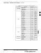
Part Number Description of Cable
01–95006–022 (six feet) DB–9S to DB–9P
01–95010–022 (ten feet)
The control port cables can be used to connect the shelf to:
3