
User's Manual

Span Lines – Interface and Isolation
PRELIMINARY
1X SCt4812ET Lite BTS Optimization/ATP
08/01/2001
3-14
T1/E1 Span Interface
At active sites, the OMC–R/CBSC must disable the BTS
and place it out of service (OOS). DO NOT remove the
span line cable conectors until the OMC–R/CBSC has
disabled the BTS.
IMPORTANT
*
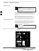
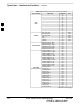
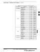
Each frame is equipped with one 50–pair punchblock for spans,
customer alarms, remote GPS, and BTS frame alarms. See Figure 3-9
and refer to Table 3-5 for the physical location and punchdown location
information.
Before connecting the LMF computer to the frame LAN, the
OMC–R/CBSC must disable the BTS and place it OOS to allow the
LMF to control the BTS. This prevents the CBSC from inadvertently
sending control information to the BTS during LMF–based tests.
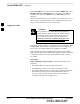
Isolate BTS from T1/E1 Spans
Once the OMC–R/CBSC has disabled the BTS, the spans must be
disabled to ensure the LMF will maintain control of the BTS. To disable
the spans, disconnect the cable connector for the BTS–to–CBSC
Transcoder span at the Span I/O card (Figure 3-7).
If the BTS is a multi–frame logical BTS, do not disconnect
the inter–frame span.
IMPORTANT
*
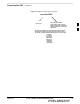
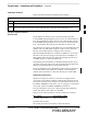
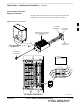
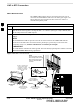
Figure 3-7: Disconnecting Span Lines
Span Line Cable
Connectors
4812ETL0020–1
3